4
OPERATION GUIDE
2-450174-030A
WWW.VARI-LITE.COM
GENERAL
This manual describes the operation and setup of the dimmer rack. It does not contain information about
installing the rack. See the separate C21 or the EC21 Dimmer Rack Installation Manual for detailed information
concerning installation and wiring of the dimmer rack.
SPECIFICATIONS
For the latest specifications for C21 / EC21 dimmer racks and dimmer modules, refer to the product datasheets
available for download on the website at www.vari-lite.com.
RACK COMPONENTS
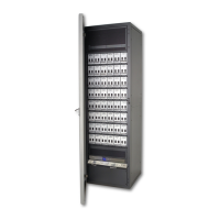
The C21 / EC21 dimmer rack is a listed, free standing, factory assembly of steel and aluminum construction fin-
ished in a fine textured, scratch resistant coating.
Each C21 / EC21 dimmer rack consists of a rack processor housing (RPH) with one or two rack processor
modules (RPM), a fan module, and up to 24 or 48 dimmer modules. The dimmer connectors at the back of the
rack provide for load wire connection. Main bus bars are provided for line wire connections. An earth ground
lug is provided in the rack. The dimmer connectors in the rack are polarized to prevent dimmer modules being
plugged into the dierent ampacity slots. The dimmer racks can be individually fed or bused together using an
optional busing kit.
Large dimmer racks have provision for up to 48 dimmer modules. Small dimmer racks have provisions for up
to 24 dimmer modules. Dimmer modules contain one, two or four dimmers, and dimmer module types can be
mixed within a rack in various combinations.
FIGURE 1. C21 / EC21 DIMMER RACK FULLY POPULATED
DIMMER MODULES
The power modules are the high power switching section of the C21 / EC21 dimming system. The power block
in this module is the interface between the high power AC and low power control. It is driven by low level sig-
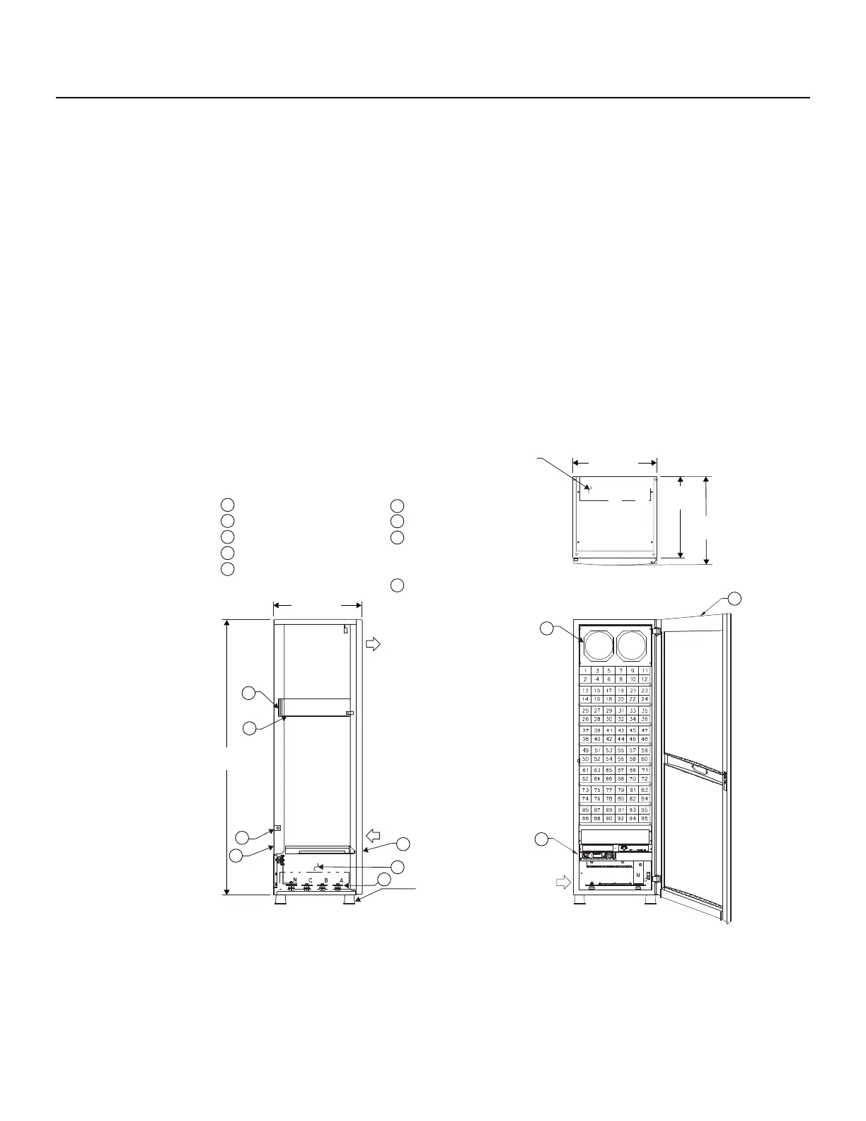
1 RJ45 ETHERNET JACK
2 DIMMER MODULES
3 MODULE TRAYS
4 FAN MODULE
5 SIGNAL TERMINATION BOARD
6 PROCESSOR MODULE
7 FEED WIRING CHAMBER
8 3-PHASE, 4-WIRE BUS
(short circuit rating = 50KA)
module trays
9 HINGED REMOVABLE DOOR
654.0mm
(25.75 in)
AIR EXIT
AIR ENTRY
2032mm
(80.0 in)
2
3
6
OPTIONAL
FLOOR-MOUNT
VIBRATION PADS
(#1-259-0009)
SIDE VIEW
(DOOR CLOSED)
MAIN FEED
TOP VIEW
(DOOR CLOSED)
WIRE ENTRY AREA
508mm x 178mm
(20 in x 7 in)
618.74mm
(24.36 in)
600mm
(23.62 in)
654.1mm
(25.75 in)
6
FRONT VIEW
(DOOR OPEN)
4
9
1
5
7
8