6
OPERATION GUIDE
2-450174-030A
WWW.VARI-LITE.COM
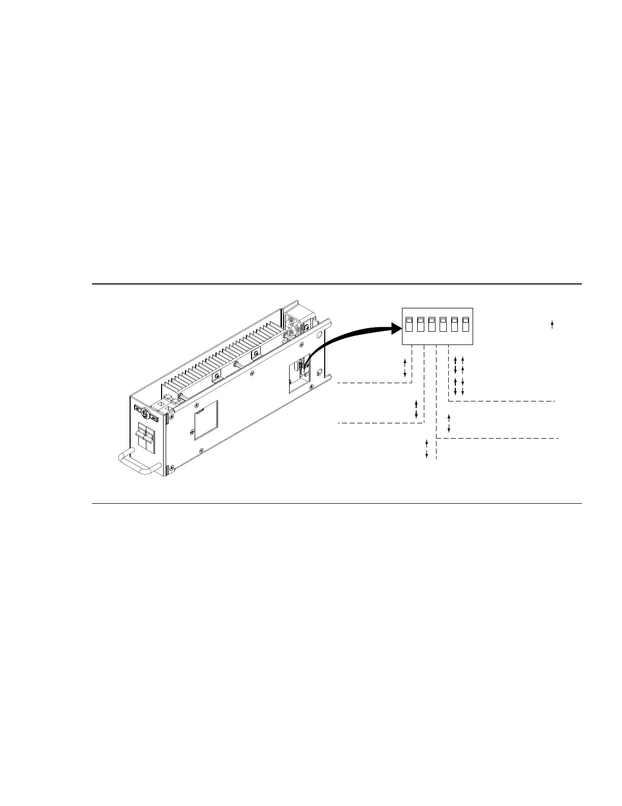
CONTROL MODE - (Factory Default ON) (Factory Default: Force FPC) Dimmer racks must be operated under
normal conditions with all dimmers configured to Force FPC. If directed by Strand Technical Support, changing
this switch to the AUTO mode position will allow the dimmer to automatically sense the load type and select
either Reverse Phase Control or Forward Phase Control, based on the load’s behavior. AUTO mode should be
used only when a load does not operate properly in the default Force FPC mode.
RPC LOCK (LED) - (Factory Default: Normal) When used in combination with CONTROL MODE = AUTO, setting
this switch to the Force RPC position locks the dimmer into reverse-phase-control only operation, which may be
required for certain LED loads. Always set this switch to Normal in all other cases.
TRANSITION CONTROL - (Factory Default Automatic) Automatic operation allows the IGBT dimmer to monitor
and adjust its transition control (up to 1000uS in 120V installations, and up to 650uS in 230V installations)
based on several operational factors. The “Fixed at 400uS” position should ALWAYS be used when the dimmer
is operating a phase-controlled electronic ballast or LED driver as its load, because these devices expect fixed
transition times for proper dimming level selection.
FULL OUTPUT VOLTAGE - (Factory Default: 120V / 240V) These switches select the RMS output voltage to be
delivered by the dimmer when the control level is 100%. Choose a non-default value if lamps of a lower voltage
rating (e.g., 115V on 120V) are used in the lighting rig.
PREHEAT - (Factory Default: Preheat Disabled) When changed to the non-default position (Preheat Enabled),
the dimmer will generate a very low voltage to the loads, when they are “o”, to keep the filaments heated,
improving response time. This feature should only be enabled on larger-wattage, incandescent lamps and only
when faster turn-on response is required.
CAUTION: It is never recommended to set the switches to Reverse Phase Control (RPC) for an entire rack of
IGBT modules.
FIGURE 3. DIP SWITCH SETTINGS
FAN MODULE
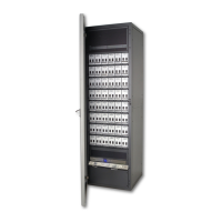
C21 / EC21 dimmer racks are cooled by one or two low-noise variable speed fans in a fan module inside the
rack. The cooling system is designed to let the rack continue functioning if any one of the fans fail. Cooling air
is pulled up through the dimmer stack and exhausted through venting at the top of the rack. These fans are for
dimmer cooling only, and can be set to fixed or variable speeds.
The fixed speed fan setting is for situations where changes in ambient noise are a problem. With this setting, the
fans are always ON when the dimmer rack is in operation.
The variable speed fan setting minimizes noise and maximizes fan life. With this setting, the fan speed is adjust-
ed so that fans reach full when 24 dimmers are at full, or equivalent (e.g., 48 dimmers at 50%). Increases in fan
speed take 1 minute with this setting, while decreases in fan speed take 5 minutes. Fans are turned OFF when
no dimmers are in use.
Fan and dimmer module choke noise may be acoustically objectionable. C21 / EC21 dimmer racks should be
installed away from performance, stage and audience areas.
O N
1
2 3 4 5 6
CONTROL MODE
Switch 1:
-Force FPC
-Auto (RPC/FPC)
RPC LOCK (LED)
Switch 2:
-Normal Operation
-Force RPC
TRANSITION CONTROL
Switch 3:
-Automatic
-Fixed at 400us
FULL OUTPUT VOLTAGE
Switches 5 & 6:
-120V (240V)
-115V (230V)
-110V (220V)
-100V (200V)
PREHEAT
Switch 4:
-Preheat Disabled
-Preheat Enabled
DEFAULT
All Switches Up (ON)
 Loading...