7
OPERATION GUIDE
2-450174-030A
WWW.VARI-LITE.COM
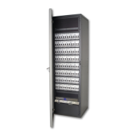
FIGURE 4. FAN MODULE
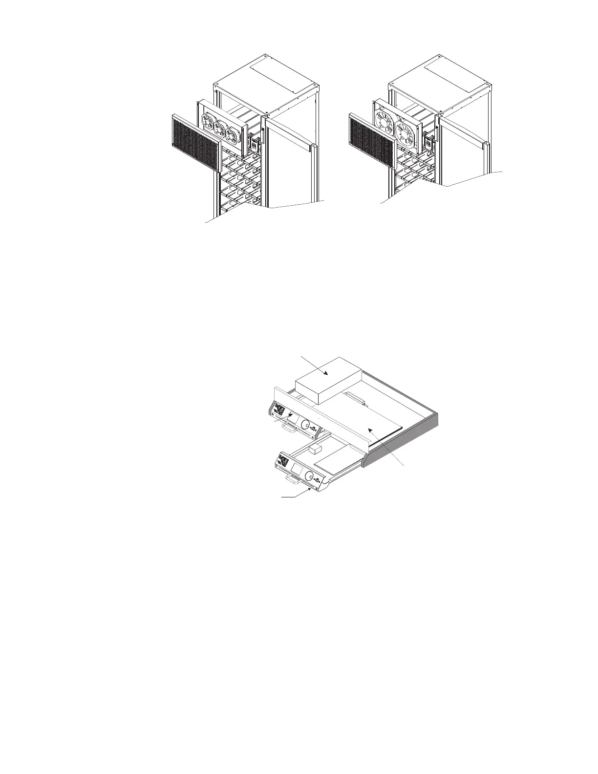
RACK PROCESSOR HOUSING
Each C21 / EC21 dimmer rack contains a rack processor housing (RPH) with all of the control electronics for the
rack. This RPH contains the processor module(s) (RPM), control station power supplies, and control interconnec-
tion card (CIC) for the rack, and is shipped separately from the rack to minimize the possibility of damage.
This chassis can be equipped with one or two processor modules. The second processor module acts as a
backup. The configuration data from either processor can be transferred into the other processor. The currently
inactive processor always tracks the currently active processor.
FIGURE 5. RACK PROCESSOR HOUSING
RACK PROCESSOR MODULE
Each C21 / EC21 dimmer rack contains one or two rack processor modules (RPM). Each processor module has a
backlit LCD display, a 7 key keypad, and 6 LEDs to report processor module and dimmer status and allow setup
and control at the rack. In normal operation, this display normally shows the rack name and the OK message. If
there are any rack or dimmer events reported, the display will show error messages.
Pressing the < or > keys will takes you into a series of setup menus to view and set up the more frequently used
C21 / EC21 features. See Section 3, Processor Module Programming for details on accessing these functions.
All programmed data is held in battery maintained RAM for up to 6 months without power.
24 MODULE RACK
48 MODULE RAC
Fan Module
an Module
Interconnection
Card (CIC)
ack Processor
Backup
Processor
Module
Power
Supplie