8
OPERATION GUIDE
2-450174-030A
WWW.VARI-LITE.COM
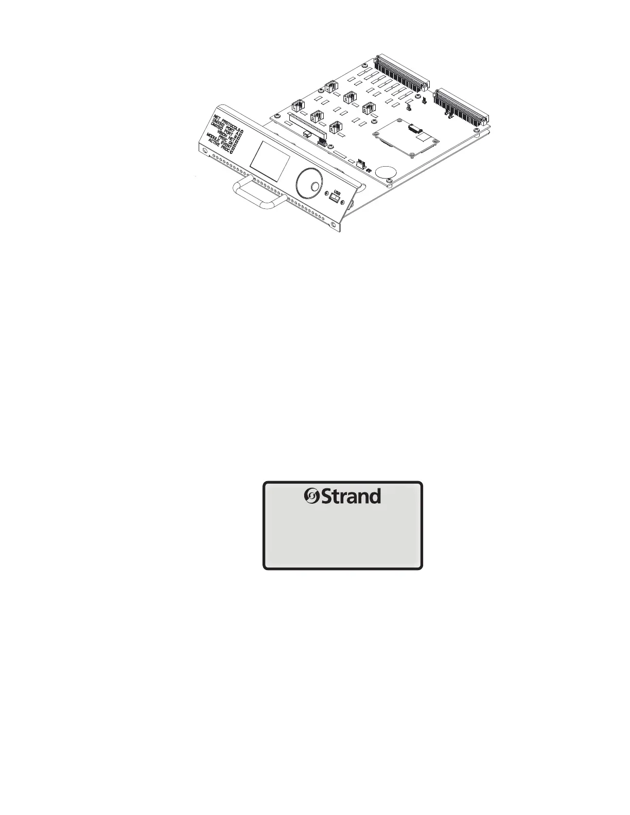
FIGURE 6. RACK PROCESSOR MODULE
POWER SUPPLIES
Each C21 / EC21 dimmer rack can have up to three power supplies, depending on the accessories provided.
These power supplies are mounted on the rack processor housing.
CONTROL INTERCONNECTION CARD (CIC)
The electronics chassis also contains the control interconnection card (CIC). This is where the contractor termi-
nates all control wiring for the rack. All control terminal strips are 2-part plug-in strips so that the electronics
chassis can be easily removed from the rack.
PROCESSOR CONFIGURATION
Once you have applied power you need to make sure that the system is working correctly and the processor
modules are set properly for the installation. This step checks for any problems due to shipping or installation.
Startup
When the rack is switched ON, a number of self-tests are run. The system displays the rack name.
When the self-tests are complete the PROCESSOR OK LED on the front of the processor module will turn ON,
and the default text will show on the LCD display.
Rack 1
xxxV xxxV xxxV
xxHz
< or > to select menu