5
OPERATION GUIDE
2-450174-030A
WWW.VARI-LITE.COM
nals (5mA, 3-24V) and switches high level signals (up to 100A, 120/240VAC). High specification filtering, SCR
dimming, contactor non-dims, IGBT dimming, and load status reporting electronics are available as options.
Dimmers can be mixed in any combination in a rack. This lets you use the exact dimmer type needed for each
circuit.
Power modules are constructed from aluminum, folded to form three sides of the dimmer and to support the
dimmer connector and heatsink. The fourth side of the dimmer is formed by the heatsink. The top and bottom
of the dimmer are open for cooling.
A sturdy handle is provided below the circuit breakers. An optional mechanical locking bar on the dimmer tray
secures the dimmers in the rack.
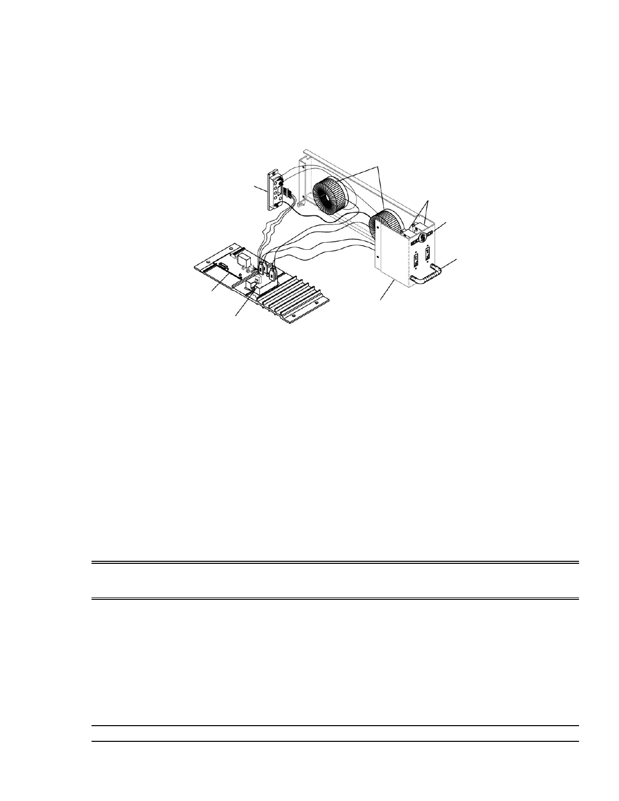
FIGURE 2. DUAL DIMMER MODULE
REPORTING DIMMER MODULES
Most C21 / EC21 dimmer modules are available in load status reporting versions. Load status reporting versions
of dimmers can be mixed in any combination with standard dimmers in C21 / EC21 racks. These dimmers report
many dimmer status items back to the processor. The information can be accessed through various menu items.
The processor can then display a wide range of faults and diagnostic data.
Each Reporting dimmer module contains a temperature sensor which will shut it down if it overheats. Anything
causing overheating in the rack will cause a gradual shutdown as each Reporting dimmer module overheats.
IGBT DIMMER MODULES
C21 / EC21 IGBT electronic dimmers provide users with exceptionally quiet and ecient dimming for a wide
range of loads. Each IGBT dimmer features forward and reverse phase control operating modes suitable for
dimming incandescent and low voltage loads as well as a broad range of LED loads.
All C21 IGBT dimmers oer low insertion loss and microprocessor controlled over current and short circuit pro-
tection. Resetting the dimmer to zero percent (0%) from the control system will restore operation in the event
of a module shutdown.
WARNING: Make sure that the neutral wire is landed correctly with its corresponding load wire for proper
operation (see the C21 or EC21 Installation manual for more information). Failure to do so will cause the dimmer
module to shut down.
Since the IGBT dimmer module monitors the dimmer rack power feed at all times, it is imperative that the power
feed is clean and free of any distortion.
In the presence of poor quality power with significant mains disturbances, the IGBT dimmer module may shut
down to protect the IGBT power devices.
IGBT dimmer modules should be configured as “Sinewave” module types when configuring the C21/EC21 dim-
mer rack processor.
IGBT DIMMER MODULE SWITCH PACK
The DIP Switches located at the side of the IGBT dimmer module allow for configuration of dimmer options.
NOTE: Dual-channel modules have a separate switch pack for each channel.
Connector
Reporting PCB
(optional)
SSR or SCR Pack
Chokes
Circuit Breakers
Dimmer Wing
With Type & Rating
Handle
Chassis
 Loading...