Theme Plus Issue 2.1 28/06/01 Page 3 of 12
Installing the fire
Site preparation
The Straxgas Theme Plus must be installed on a level, non-combustible hearth in accordance
with BS5871, Part 2. See also approved document J 1/2/3 "Heat Producing Appliances" issued
by the Department of the Environment.
Clear the working area of all debris before removing the Straxgas appliance from the
packaging.
Items supplied
The following items will be found within the carton:
1. Convection box.
2. Separate flat trim, optional canopy trim, or spacer frame with box trim depending on
options ordered.
3. Burner complete with controls
4. Restrictor plate, (use depends on type of installation).
5. Optional fret.
6. 1 back, 1 centre, & 2 front ceramic sections.
7. Coals (6 large, 4 small)
8. Foam sealing strip
9. Screws and wall plugs to complete the installation.
10. These installation instructions, guarantee card and end user operating instructions.
Warning: Only Straxgas approved ceramic blocks and coals, designed for this appliance,
must be used with this burner. Use of ceramic components from any other supplier will
invalidate the guarantee and may be dangerous.
When unpacking the appliance, avoid touching the visible, painted parts as the paint requires
curing (this will take approximately 2 hours under fire. In some cases there may be a slight
odour given off for a short period).
Fret options
The following Straxgas frets are suitable for use with this appliance:
• Black finger (brass or stainless finials &ash pan ring)
• Brass finger
• Stainless finger (polished or satin)
• Classic, Silver Classic
• Gainsborough (all brass or black)
• Delta (polished or satin)
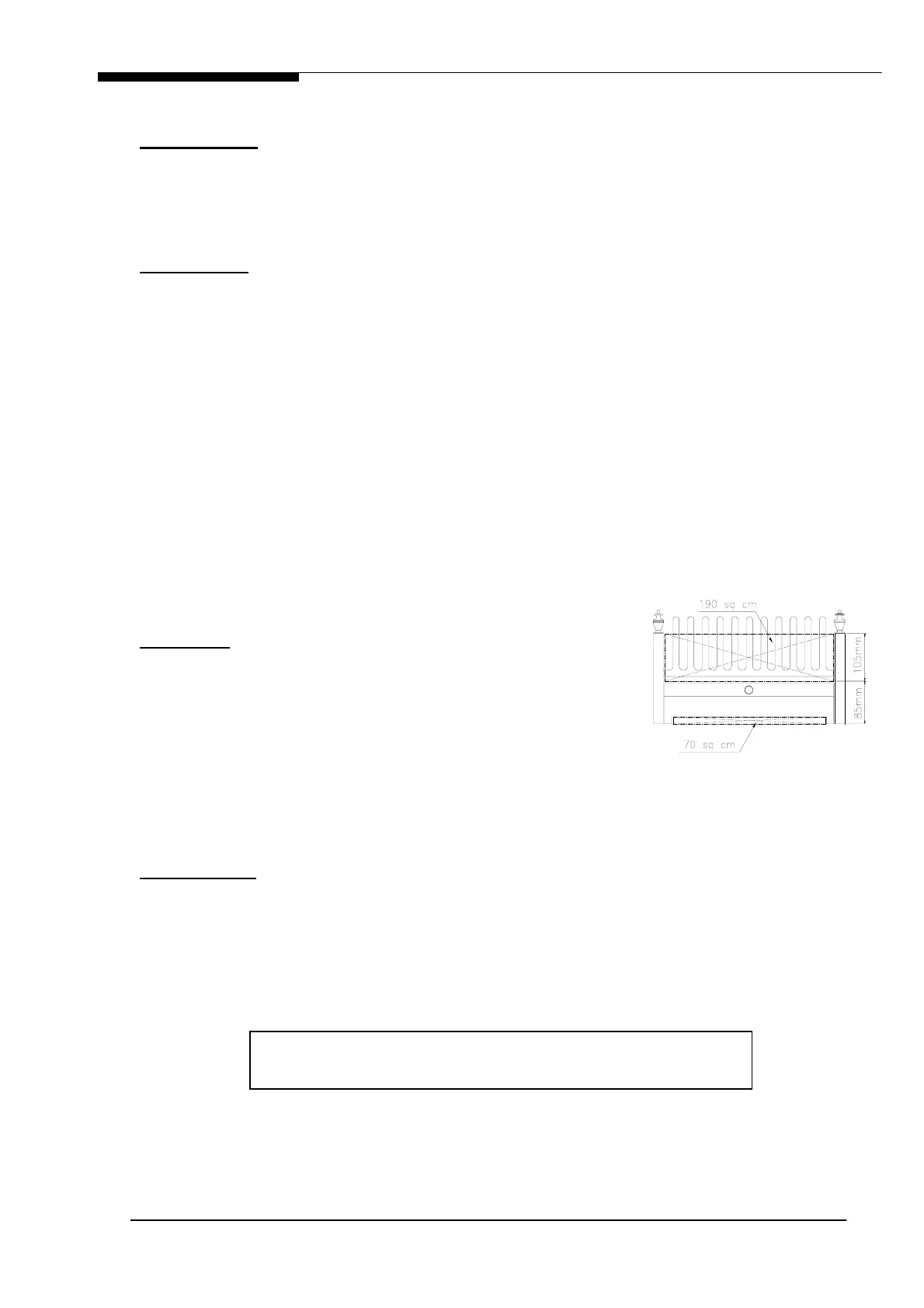
If a fret from another manufacturer is being used, it must comply with the minimum free area
requirements shown in Fig. 1.
Gas connection
Note: Gas connection shall be with rigid or semi-rigid pipe, by concealed connection only. A
15mm (10mm for propane) gas supply pipe with isolation cock should be brought to within 1M
of the fireplace opening. The connection to the burner can be made from the right or left-hand
side by a concealed pipe from behind the burner to the elbow on the left-hand side of the
burner. Use a pre-punched hole in the convection box to allow the gas supply pipe to be
installed. 8mm pipe is required for this purpose.
When passing the pipe through brickwork or plaster, cap the end to prevent entry of debris.
Fig. 1 Optional fret min.
ventilation re
uirement
WARNING: Always blow pipework through before connecting to
appliance - contamination will permanently damage the burner.