Page 14
23/03/01
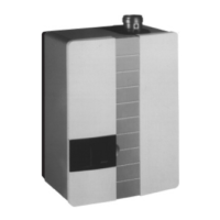
ASSEMBLY INSTRUCTIONS FOR: Ca 7s / BCa 7s
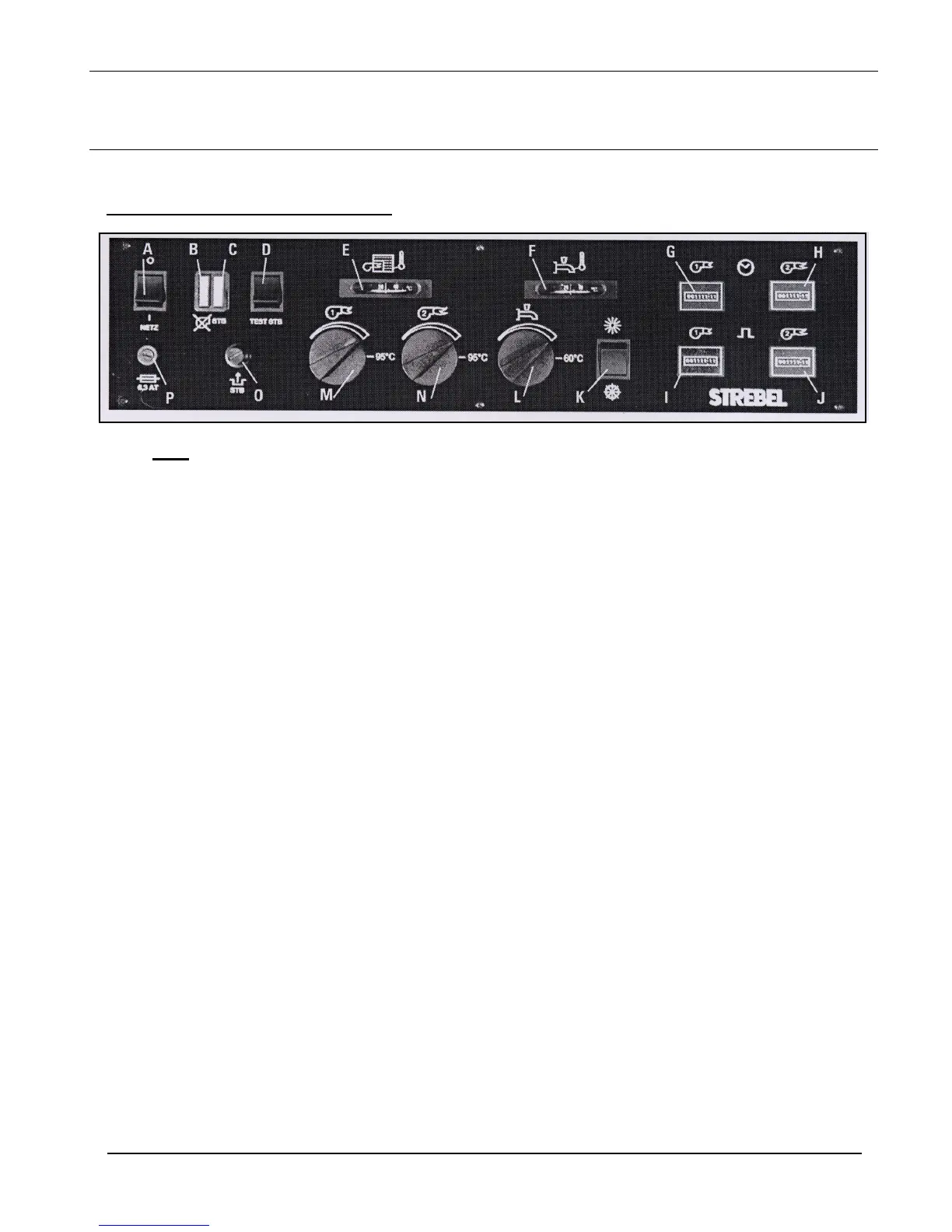
Instrument Control Panel Description
Key:
A. Power On / Off switch.
B. Burner lock-out indicator. (RED) - The red lamp will illuminate if the burner has gone to lock-out.
C. High limit indicator. (ORANGE) - Illuminates if the high limit thermostat is activated. Has to be
manually reset by removing cap from STB reset, and press button.
D. High Limit Test Switch. (STB) - Overrides the control thermostat to enable limit thermostat test.
E. Boiler Thermometer– Shows the actual boiler water temperature and has no influence on boiler
temperature control.
F. HWS Thermometer - Shows temperature of the HWS calorifier. (B2B version only)
G. Hours Run Meter (blanked as standard) Burner Stage 1 - Shows running time of the stage 1 burner
operation.
H. Hours Run Meter (blanked as standard) Burner Stage 2 - Shows running time of the stage 2 burner
operation.
I. Frequency of Switching Meter for Stage 1. (blanked as standard).
J. Frequency of Switching Meter for Stage 2. (blanked as standard).
K. Summer / Winter Switch - For switching boiler between modes to supply HWS only in the summer
period.
L. Calorifier Control Thermostat - Set for the required hot water temperature (60ºC Max.)
M. Control Thermostat - Stage 1.
N. Control Thermostat - Stage 2.
O. Boiler Safety Limit Thermostat (STB) - Manual reset. Used when the boiler water temperature
overheats. The water in the boiler must cool to around 80ºC, to enable reset. (refer to point “C”
above).
P. Fuse (6.3A) - Protection for all the controls and any ancillary equipment connected back to the
control panel. A defective fuse MUST be replaced with an identical one.
ATTENTION: Before a fuse is replaced, the instrument control panel must be isolated.