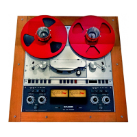
www.SteamPoweredRadio.Com
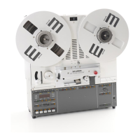
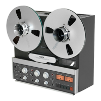
Teclas del mecanismo de arrastre
Las
teclas de mando del mecanismo de arrastre
no requieren
mas
que una leve presi6n.
Estas
teclas, de
la
(j)
a
la
@ ,
se
puede apretar
en
cualquier secuencia sin miedo a
producir
alguna
averia,
ya
que todas
las
funciones estan entre-
lazadas electr6nicamente y
cada
orden
de
mando queda almacenada
en
la
memoria del
aparato.
®
PAUSE
Esta
tecla bloquea mientras
esta
apretada
cua
l-
quier
movimiento
de
la
cinta. Cuando
se
suelta,
se
reanuda
el
movimiento
interrumpid
o
en
la
misma forma
en
que estaba antes
de
apretarla.
(Para
pausas
largas, utilicese
la
tecla de enganche
del mando a distancia.)
(j)
<<
Rebobinado
®
>>
Bobinado rapido
Accionando
el
bot6n deslizante
@,
las
teclas
de bobinado o rebobinado rapido, solo actuan
si
se
las
mantiene apretadas.
De
esta
forma
se
fa-
cilita
la
localizaci6n
de
un
punto
determinado
de
la
cinta.
Nota:
Debe evitarse
la
utilizaci6n excesiva de los
bobinados rapidos
en
esta
posici6n por
el
des-
gaste
que puede suponer para
las
cabezas
de
grabaci6n y lectura.
®
PLAY
Esta
tecla activa
la
reproducci6n.
En
cua
lquiera
de
los modos de bobinado rapido,
al
apretar
esta
tecla, entran
en
acci6n los frenos y cuando
se
llega a
la
parada completa de
la
cinta, inmediate-
mente el aparato
pasa
a reproducir.
@)
STOP
Anula todas
las
funciones
de
arrastre.
@
REC (Grabaci6n)
Para
efectuar cualquier grabaci6n,
es
necesario
~etar
simultaneamente
las
teclas
REC
y
PLAY
~-
La
tecla
REC
utilizada
so
l
a,
no tiene efecto
alguno. Lo anterior
se
debe a
una
precauci6n
suplementaria para evitar
el
borrado accidental
no deseado.
B
Panel
MONITOR
Controles
de
mando
dP
la
reprnrf ,~c,on
El
panel
Monitor
agrupa todos los mandos
de
reproducci6n. Estos no tienen ningun efecto
durante
la
grabaci6n.
@
Regulaci6n del
VO
LUMEN
Dos
potenci6metros acoplados
por
fricci6n,
regulan
el
volumen de escucha con
cascos.
El
de
mayor diametro, pegado
al
panel, actua sabre
el
canal izquierdo y
el
de menor diametro, sabre
el
derecho.
Se
puede ajustar
el
balance
de
la
es-
cucha, girando uno u
otro
de los potenci6-
metros
mas
o menos que
el
otro.
@
lndicador
de
nivel
LEFT
CHANNEL
(Canal Izquierdo)
@
lndicador
de
nivel
RIGHT
CHANNEL
( Canal derecho)
Segun
sea
la
posici6n del conmutador
TAPE/
INPUT
@.
los indicadores reflejan el nivel de
la
serial
de reproducci6n, o
el
de
la
serial de
6
Tape transport buttons
The tape transport
buttons
(j)
to
@
need
only
to
be tapped
to
activate the desired func-
tion.
They
may be operated
in
any sequence
without
hesitation, because
al
l functions are
electrically interlocked and
each
command
is
stored electronically.
®
PAUSE
This
button
interrupts any tape
motion
as
long
as
it
is
kept depressed. When releasing this
but-
ton, the originally selected operating mode r
e-
sto
re
s itself. (
For
extended
interruptions
use
locking
button
on the remote co
ntr
ol device.)
0
<<
FAST
REWIND
® >>
FAST
FORWARD
With
the
sliding
button
@
in the
cutter
posi-
tion,
the
buttons
for
fast forward and rewind
will
respond
only
as
long
as
they
are being held
depressed. This facilitates
motor
assisted search
operations
by
s
imply
alternating between these
two
buttons.
Note
:
In order
to
keep headwear
to
a
minimum,
do
not
wind long sections
of
tape in the
cutter
position.
®
PLAY
Activates the reproducing mode. When pushin'g
this
button
during either fast wind mode, the
recorder
will
first come
to
a
full
stop,
which
is
then followed immediately
by
the activation
of
the reproducing mode.
@)
STOP
Cancels any
se
lected tape transport mode.
@
RECord
To activate the recording mode, the
buttons
REC and
PLAY
@
have
to
be
pressed
simu
l-
taneously. The
button
REC remains
without
any
effect
when pressing
it
alone. (Protection
against unintentional recording
or
erasure
of
a
tape.)
B
MONITOR
panel
Reproduce operat1n controls
All
operating
contro
ls that are required during
the reproduction
of
a tape
are
combined on
the
monitor
panel.
@
VOLUME
The tandem
potentiometer
VOLUME
varies the
leve
l
for
headphone listening. The innermost
potentiometer acts on the
left
channel while the
right channel
is
contro
ll
ed
by
the potentiometer
on the
front.
Both
controls
are
connected via a
slip-clutch thus
permitting
their individual ad-
justment
to
achieve the desired balance.
@
Recordi
ng
leve
l indicator
LEFT
CHANNEL
@
Recording
level
indicator
RIGHT
CHANNEL
The modulation meters indicate either the
re-
produced level
from
tape
or
the
input
level
during recording (depending on the position
of
Tasto
per
ii
trasporto del nastro
I tasti di comando
da
(j)
a
@
necessitano
solo di una
leggera
pressione.
La
memorizza-
zione
ed
ii blocco delle funzioni sono completa-
mente e
lettronici;
i tasti possono
essere
mani-
polati
senza
seguire alcun ordine.
®
PAUSA
Ouesto tasto blocca momentanamente
le
fun-
zioni in corso. Dette ritornano attive quando ii
tasto viene rilasciato.
(Per
delle lunghe
pause,
usare
ii tasto di arresto del comando a distanza.)
0
<<
Riavvolgimento
® >>
Avvanzamento rapido
Azionando ii pulsante di montaggio
@
i tasti
di avvolgimento rapido agiscono solo quando
sono premuti. Manovrando i tasti di avvolgimen-
to
rapido, l'individuazione
sul
nastro
si
fa
piu
agevolmente.
Nota:
Al
fine di non logorare
le
teste
magne-
tiche,
si
raccomanda di non avvolgere lunghi
tratti
di nastro con ii pulsante di montaggio
in
azione.
®
PLAY
Ouesto tasto comanda
la
lettura.
11
passaggio
da
avvolgimento rapido in lettura
si
fa rapida-
mente. L'apparecchio
si
mette subito in
fase
di
frenaggio e
dopa
l'arresto completo del nastro,
passa
automaticamente in lettura.
@)
STOP
Annul
la
tutte
le funzioni.
@
REC (Registrazione)
Per
ii
coman
do
di registrazione
e
necessario
pre mere contemporaneamente i tasti
REC
e
P
LAY
@.
11
tasto
REC
uti
I izzato
da
solo
res
ta
senza
effetto;
cio per evitare false manovre o di
cancellare accidentalmente un nastro.
B
Parte
MONITOR
Organi
d1
controllo
an
lettura
La parte
monitor
raggruppa
tutti
i comandi di
lettu
ra
che non hanno alcun
effetto
in
registra-
zione.
@
Regolazione del volume
Due potenziometri accoppiati a mezzo di
fri
-
zione regolano
ii
volume dell'ascolto
in
cuffia.
La
manopola centrale agisce
sul
canale sinistro e
la
manopola esterna
su
quello destro.
Una
mo-
difica
della regolazione
e
possibile girando un
potenziometro
o
l'altro
in
senso
inverso.
@
lndicatore
di
livello
LEFT
CHANNEL
(canale
sin
istro)
@
lndicatore
di
livello
RIGHT
CHANNEL
(canale destro)
Seguendo
la
posizione del commutatore
TAPE/
INPUT
@
gli indicatori danno ii livello del
segnale di lettura o del segnale di entrata per
la
 Loading...