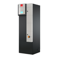
Do you have a question about the Stulz Split-Air CST 50 and is the answer not in the manual?
| Brand | Stulz |
|---|---|
| Model | Split-Air CST 50 |
| Category | Air Conditioner |
| Language | English |
Stops compressor when refrigeration circuit pressure exceeds set value.
Stops compressor when refrigeration circuit pressure drops below set value.
Microprocessor-based board for unit control, optional telemonitoring link.
Instructions for connecting and configuring multiple units in sequence.
Procedure for modifying parameters like temperature setpoint during cooling.
Calculating sensor offset based on real vs. C1010 reading.
Configuring sensors for unit 1 and subsequent units.
Checks and requirements for indoor unit placement, including space and wall support.
Table showing pipe diameters and potential problems based on distance.
Table for calculating additional refrigerant charge based on piping distance.
Rules for routing, insulation, and slope of refrigerant lines.
Specifies maximum allowed distance and height difference for connecting pipes.
Diagrams showing IN/OUT connections for evaporating and motor-condensing units.
Procedure for adding refrigerant after installation and start-up.
Details on compressor oil type, lubrication, and handling precautions.
User must furnish isolating switch and adhere to cable standards.
Guidelines for main power and DC power supply lines, polarity, and cable section.
Connecting main power supply between evaporating and condensing units.
Procedure for starting the unit using thermostat control.
Procedure for starting the unit using C1010 controller.
Diagrams showing space requirements for indoor unit maintenance.
Space requirements for horizontal indoor unit installation.
Space requirements for outdoor unit installation.
Schedule for regular checks and cleaning of unit components.
Recommendations for replacing components based on MTBF.
Instructions for cleaning the unit, including condenser and inner parts.
Keypad for displaying unit status and alarms, connected to C1010.
Discusses risks from electrical faults and safety standards.
Risks associated with high voltage contact and its effects.
Safety measures when working on the unit with power off.
Standards for maintenance on live equipment.
Safety standards to follow during maintenance operations.
Precautions for handling refrigerants and working on cooling circuits.
Warning about refrigerant gas and lubricants being pollutants.
Troubleshooting for units not cooling, with causes and remedies.
Troubleshooting for insufficient cooling, with intermittent operation.


