12
BUILT-IN FIREPLACE INSTALLATION
Built-in installation of this replace
involves installing replace into a
framed-in enclosure. This makes
the front of the replace ush with
wall. If installing a built-in mantel
above the replace, you must follow
the clearances shown in Fig. 5.
Follow the instructions
NOTICE: Surface temperatures of
adjacent walls and mantels become
hot during operation. Walls and
mantels above the replace may
become hot to the touch. If installed
properly, these temperatures meet
the requirement of the national
product standard. Follow all
minimum clearances shown in this
manual. See Fig. 6.
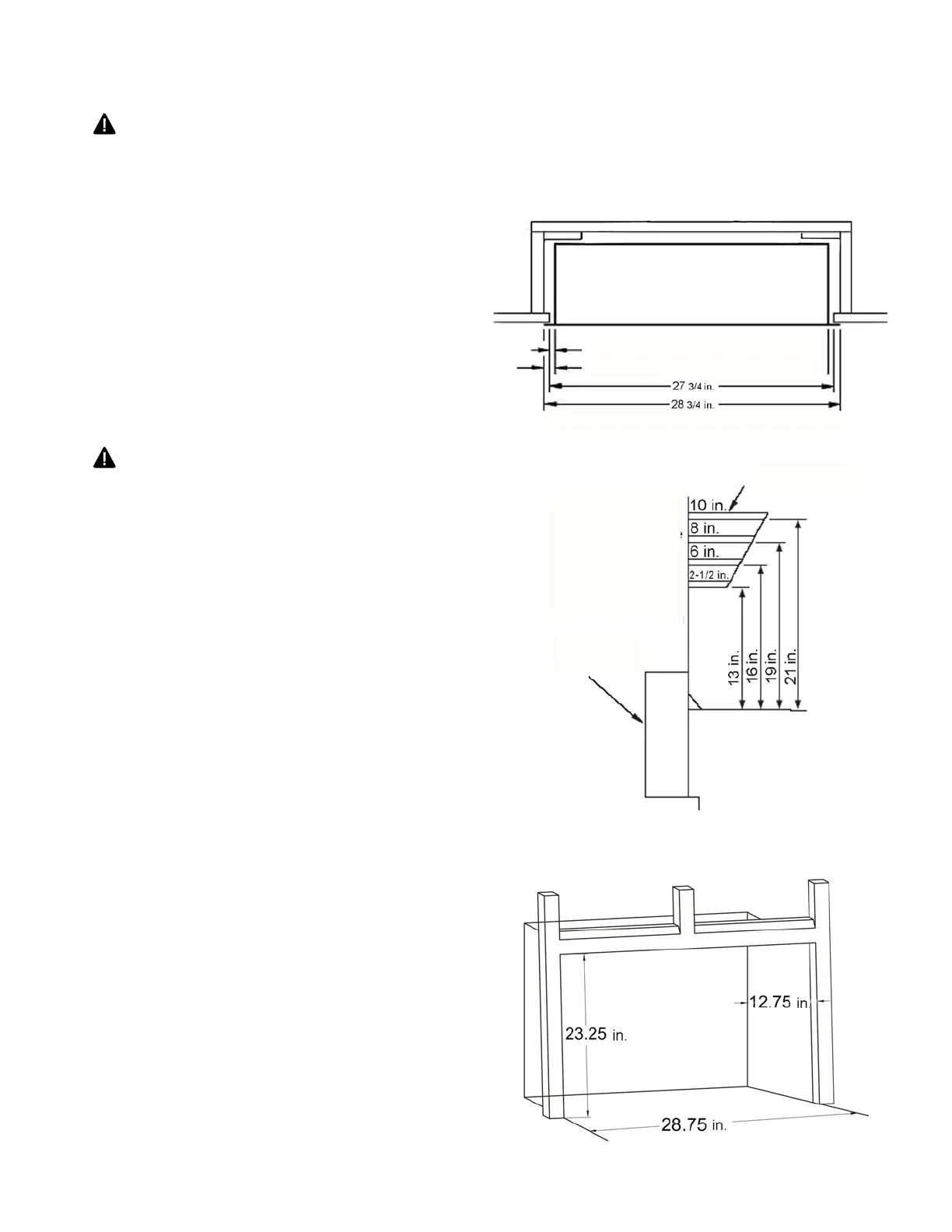
1. Frame in rough opening. Use dimensions
shown in Fig. 7 for the rough opening.
If installing in a corner, use dimensions
shown in Fig. 8 for the rough opening.
The height is 26 1/2 -in., which is the
same as the wall opening above.
2. Carefully set replace in front of rough
opening with back of replace inside wall
opening.
3. Attach gas line to replace gas regulator.
See "Connecting to Gas Supply," page 14.
4. Check all gas connections for leaks. See
“Checking Gas Connections,” page 18.
Fig. 7 - Rough Opening for Installing in Wall
Fig. 5 - Clearance to Combustibles
Fig. 6
NOTE: When heater is installed directly on carpeting, tile or other combustible material,
other than wood ooring, the heater must be installed on a metal or wood panel extending
the full width and depth of the heater.
Note All vertical
measurements are
from top of replace
opening to bottom
of mantel shelf. All
measurements are
in inches.
Side of
Firebox
Mantel Shelf
Note: Height of replace opening on facia to 23 ¼ inches
3/4 in. Clearance to facia
1
3
/
8
in. Clearance to Sides, Back and Top