15
Dimensions in parentheses are in
millimeters unless otherwise specified.
Refer to the full-
scale illustrations at
the end of this
section for specifics
on door openings
and other specifica-
tions.
INSTALLATION
Refer to the
installation instruc-
tions shipped with
each Sub-Zero
product for detailed
specifications.
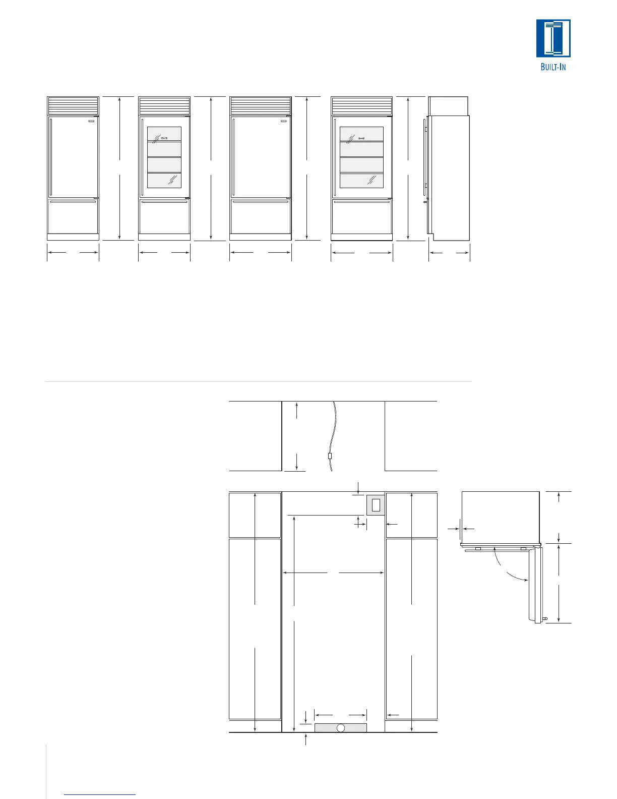
30"
(762)
84"
(2134)
36"
(914)
84"
(2134)
30"
(762)
84"
(2134)
36"
(914)
24"
(610)
84"
(2134)
83
3
/4" (2127)
ROUGH OPENING
HEIGHT TO
FINISHED
FLOORING WITH
STANDARD
11" (279) GRILLE
83" (2108)
MIN HEIGHT
REQUIRED TO
FINISHED
FLOORING
(LEVELERS IN)
75
1
/2"
(1918)
7"
(178)
6"
(152)
A
ROUGH OPENING WIDTH
24"
(610)
ROUGH
OPENING
DEPTH
E
3"
(76)
18"
(457)
W
LOCATE WATER SUPPLY
WITHIN SHADED AREA
LOCATE ELECTRICAL
WITHIN SHADED AREA
6"
(152)
SHUT-OFF
VALVE
FRONT VIEW
TOP VIEW
EXTEND
WATER LINE
APPROX 36" (914)
FROM BACK WALL
INSTALLATION SPECIFICATIONS
Over-and-Under Models
Model 611
A) Rough Opening Width 29
1
/2" (749)
B) Min Door Clearance 30
1
/8" (765)
Model 611G
A) Rough Opening Width 29
1
/2" (749)
B) Min Door Clearance 30
1
/8" (765)
Model 650
A) Rough Opening Width 35
1
/2" (902)
B) Min Door Clearance 36
1
/16" (916)
Model 650G
A) Rough Opening Width 35
1
/2" (902)
B) Min Door Clearance 36
1
/16" (916)
Dimensions are for finished rough openings.
Door swing clearances are based on
stainless steel door and handle dimensions.
OVERALL DIMENSIONS
Over-and-Under Models
OVER-AND-UNDER
Model 611
Model 611G
with Glass Door
Model 650
Model 650G
with Glass Door
B
23
7
/8"
(606)
BEHIND
FRAME
3
/8"(10)
FRAME
EXTENSION
90˚
Model 611
Width 30" (762)
Height 84" (2138)
Depth 24" (610)
Model 611G
with Glass Door
Width 30" (762)
Height 84" (2138)
Depth 24" (610)
Model 650
Width 36" (914)
Height 84" (2138)
Depth 24" (610)
Illustrations shown in stainless steel design.
Model 650G
with Glass Door
Width 36" (914)
Height 84" (2138)
Depth 24" (610)