LT. BLUE
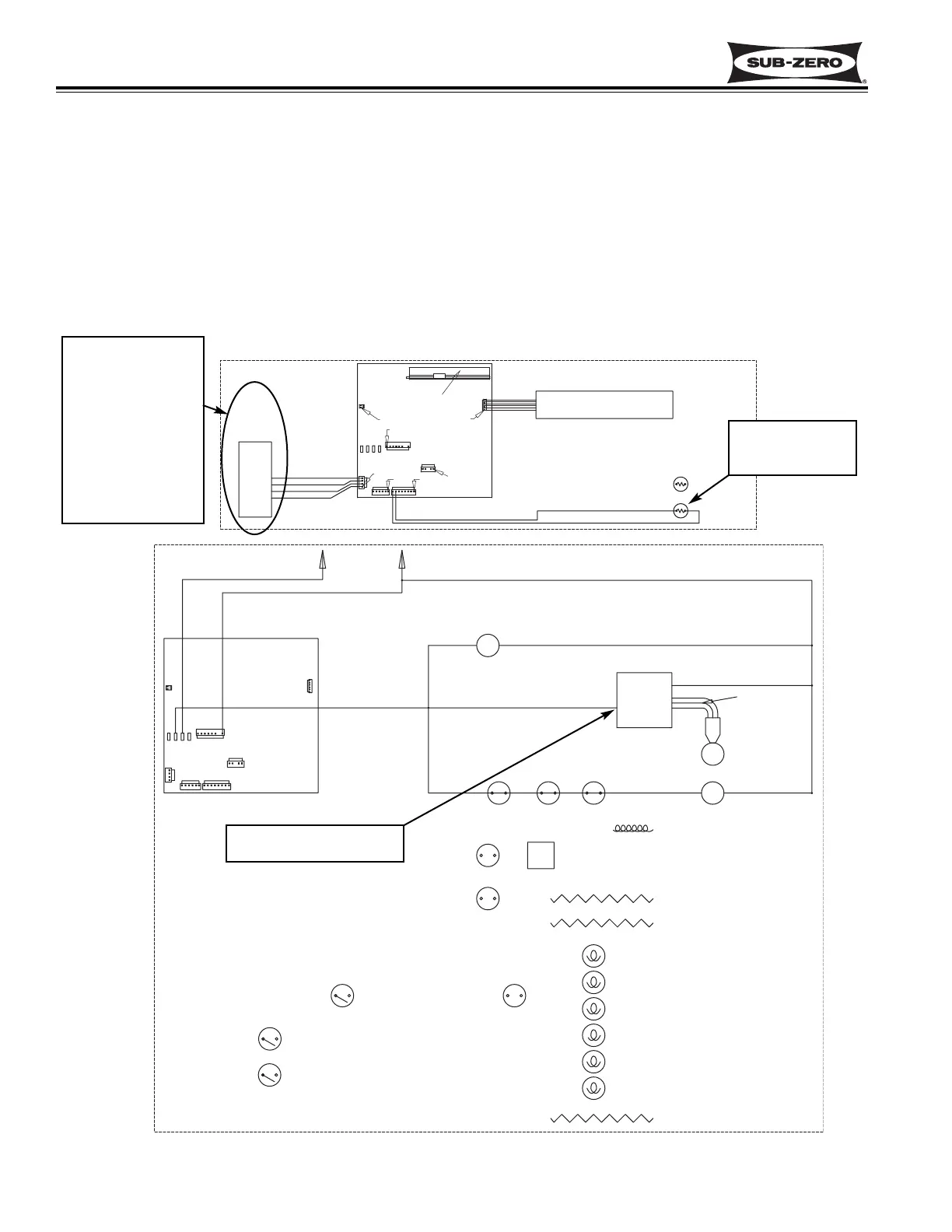
Figure 3-17. 700TF/I-2V Signal Trace Schematic of Compressor Electrical System
3. Microprocessor
monitors speed
commands sent to
compressor con-
troller. If 4000
RPM speed com-
mand is observed
continuously and
for extended peri-
ods, SERVICE
flashes on LCD.
2. 115 volts AC supplied to
compressor controller
1. High offset temp
reached, calling
for cooling
Monitor Speed Signal of Variable Speed Compressor Controller, Displays If Service may be Needed
(700TF/I-2V)
The microprocessor in the model 700TF/I-2V monitors speed commands it sends to the compressor controller (See
Figure 3-17). If the microprocessor continually sends commands to operate the compressor at highest speed (4000
RPM) for extended periods, a signal is sent to the SERVICE annunciator on the LCD to flash (See Figure 3-16).
NOTE: Speed commands will normally vary at 0, 1600, 1700, 1800, 2100, 2200, 2400, 2700, 3600 and 4000 RPM.
NOTE: Disconnected wires between the controller and J3 on the control board could also cause the SERVICE
annunciator to flash. This will be covered in the Troubleshooting Guide section of this manual.
NOTE: Also see NOTES on preceding page.