Electronic Control
Integrated (
Integrated (
700-
700-
2) Series
2) Series
3-15
#3756780 - Revision D - July, 2005
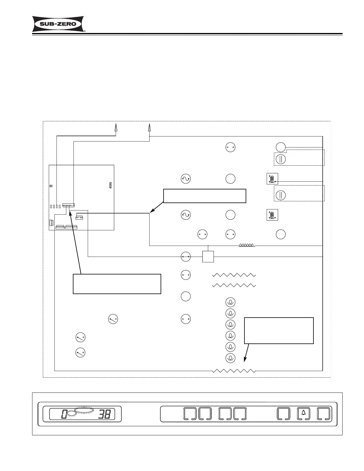
Figure 3-18. 700TC/I-2 Signal Trace Schematic (High Voltage) of Icemaker Electrical System
Figure 3-19. ICE & SERVICE Flashing if Icemaker Water Valve Solenoid Energized More Than 15 Seconds
115 Volts to solenoid is monitored
by microprocessor
If signal to solenoid lasts more than
15 seconds, power to icemaker
system is disabled
Fill tube heater is energized
whenever icemaker system
is switched “ON” and ICE
appears on LCD
Monitor Icemaker System and Display If Service Is Needed
The microprocessor monitors the 115 volts supplied to the icemaker water valve solenoid. If the solenoid is ener-
gized for more than fifteen seconds, power to the icemaker system is disabled (this does not include the fill tube
heater). A signal is then sent to the SERVICE and ICE annunciators on the LCD to flash. (See Figure 3-18 & 3-19)
NOTE: To clear the SERVICE and ICE error annunciators, the problem must be corrected, then the unit must be
switched OFF and back ON.
NOTE: To allow ice to freeze fully and reduce effects of low water pressure, the electronic control system interrupts
power to the icemaker system for 45 minutes after each ice harvest. This feature is present in the tall units only.