EasyManua.ls Logo

Sub-Zero 700-2 Series

Sub-Zero 700-2 Series
166 pages
To Next Page IconTo Next Page
To Previous Page IconTo Previous Page
Loading...
Page 41
Electronic Control
Integrated (
Integrated (
700-
700-
2) Series
2) Series
3-31
#3756780 - Revision D - July, 2005
THERMISTORS
ZONE
DISPLAY
REMOTE
TEST
P15
P1
P7
P9
P8
P14
P6
P5
P10
P11
P4P2 P3
1
1
11
1
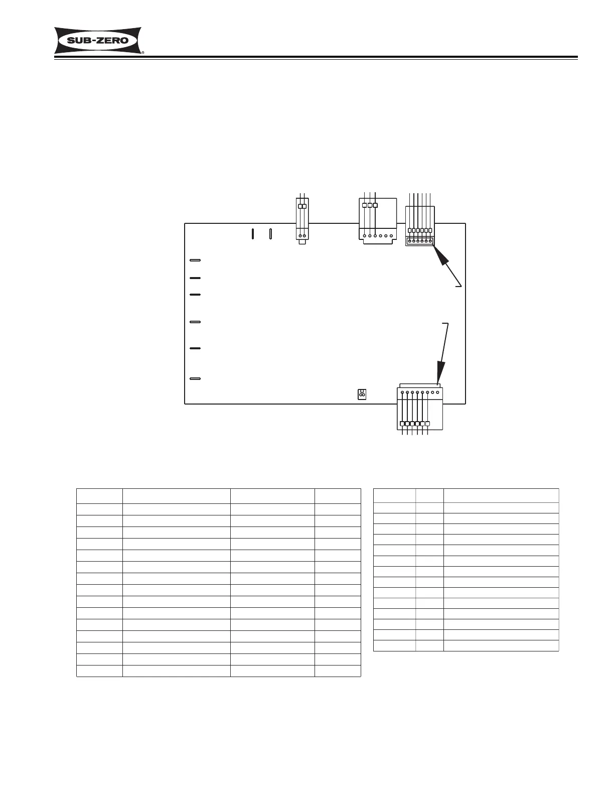
Figure 3-68. 700-2 Base Unit Control Board Layout
Figure 3-69. 700-2 Base Unit Control Board Summary Table (700BF/I-2 Summary Table Shown)
700-2 BASE UNIT CONTROL BOARD LAYOUT AND SUMMARY TABLE
The electrical connection points on the 700-2 base unit control board are labeled alphanumerically. These labels
correspond with the alphanumeric control board summary table, located on all 700 Series wiring diagrams. By refer-
encing the summary table, it is possible to identify which components are connected at which points on the control
board. Below is a layout diagram of the control board, and a copy of a summary table. (See Figures 3-68 & 3-69)
NOTE: All components on the control board are non-replaceable. If a problem with the control board is identified,
the complete control board must be replaced.
------
LT. BLUE W/YELLOW
BLUE W/BLACK
BLUE W/BLACK
AUXILIARY CHART
EMPTY
BLUE W/RED
TERM.
No#
P3 1
2
3
4
5
6
COLOR
BLACK
------
JUMPER
SEE AUX. CHART -----
SEE AUX. CHART
P2
EVAPORATOR FAN
WHITE/RED
RED
P3
ICEMAKER SWITCH
P4
PINK
REMOTE DISPLAY
BLACK
P5
-----
WHITE
PINK
P6
------
BLACK
-----
P7
COMPRESSOR
ORANGE
PURPLE
MANUFACTURING TEST
BLUE
TESTP15
WHITE
RED
YELLOW
ORANGE
BLUE
BLUE W/RED
THERMISTORS
TERM.
EMPTY
DESCRIPTION
COLOR
ABBR.
LT. BLUE W/YELLOW
P1
P8
LIGHT SWITCH
RED
WH/RD
P9
P1
-----
BLACK
1
2
BAFFLES
3
4
P10
-----
------
5
P11
L2-NEUTRAL 115 WHITE
P12
L1-HOT 115
------
BLACK
P13
6
LIGHTS-115V OUT
PURPLE
ORANG
P14
7
8
DEFROST HEATER
------
BLUE

Related product manuals