Component Access/Removal
Integrated (
Integrated (
700-
700-
2) Series
2) Series
7-7
#3756780 - Revision D - July, 2005
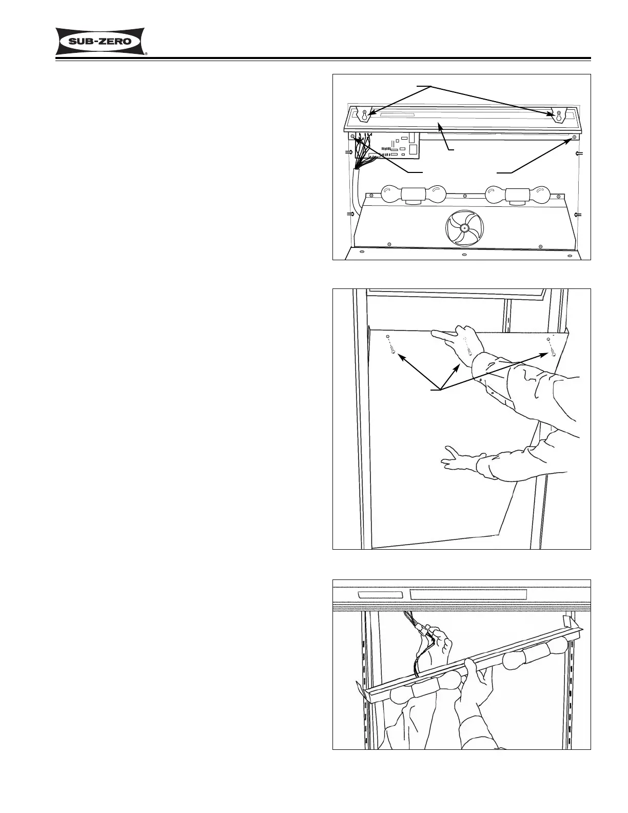
Control Panel Assembly Removal (All Tall Units)
The control panel is held in place with two rows of
screws. The front row of screws go through spacers
that fit into key-hole slots at the front of the panel. The
rear screws secure the assembly to the ceiling.
To access and remove the control panel, the light dif-
fuser and control enclosure must be removed first.
NOTE: It is recommended but not necessary to remove
the control board in order to remove the control panel.
If leaving the control board secured to the control panel,
all electrical leads attached to the control board must be
disconnected.
Then, extract the back screws and push the panel
towards the rear of the unit to release the front screws
from the key-hole slots, then lower the panel down and
pull out. (See Figure 7-13)
Upper Evaporator Cover / Air Duct Removal
(All Tall Units)
The bottom of the upper evaporator cover sets into a
channel at the bottom of the upper compartment. At
the top, screws hold the evaporator cover to the evapo-
rator fan shroud.
To access and remove the evaporator cover, the light
diffuser must first be removed. Then, extract the
screws at the top of the evaporator cover, tilt the cover
forward and lift out. (See Figure 7-14)
Upper Evaporator Fan Shroud Assembly Removal
(All Tall Units)
The evaporator fan shroud assembly, which holds the
upper compartment lighting components, is secured to
the ceiling with five screws, two at the rear and three at
the front. (See Figure 7-13)
To access and remove the evaporator fan shroud
assembly, first remove the light diffuser and evaporator
cover. Then, extract the five mounting screws which
secure the fan shroud assembly to the ceiling of the
compartment. Lower the assembly and disconnect the
wiring for the lights from the wire harness. (See Figure
7-15)
Figure 7-13. Control Panel Removal
Mounting Screws
Key-Hole Slots
Control Panel
Figure 7-14. Upper Evaporator Cover Removal
Figure 7-15. Upper Evaporator Fan Shroud Assy
Evap Fan Shroud
Assembly
Disconnect Wiring
Screws