Component Access/Removal
Integrated (
Integrated (
700-
700-
2) Series
2) Series
7-6
#3756780 - Revision D - July, 2005
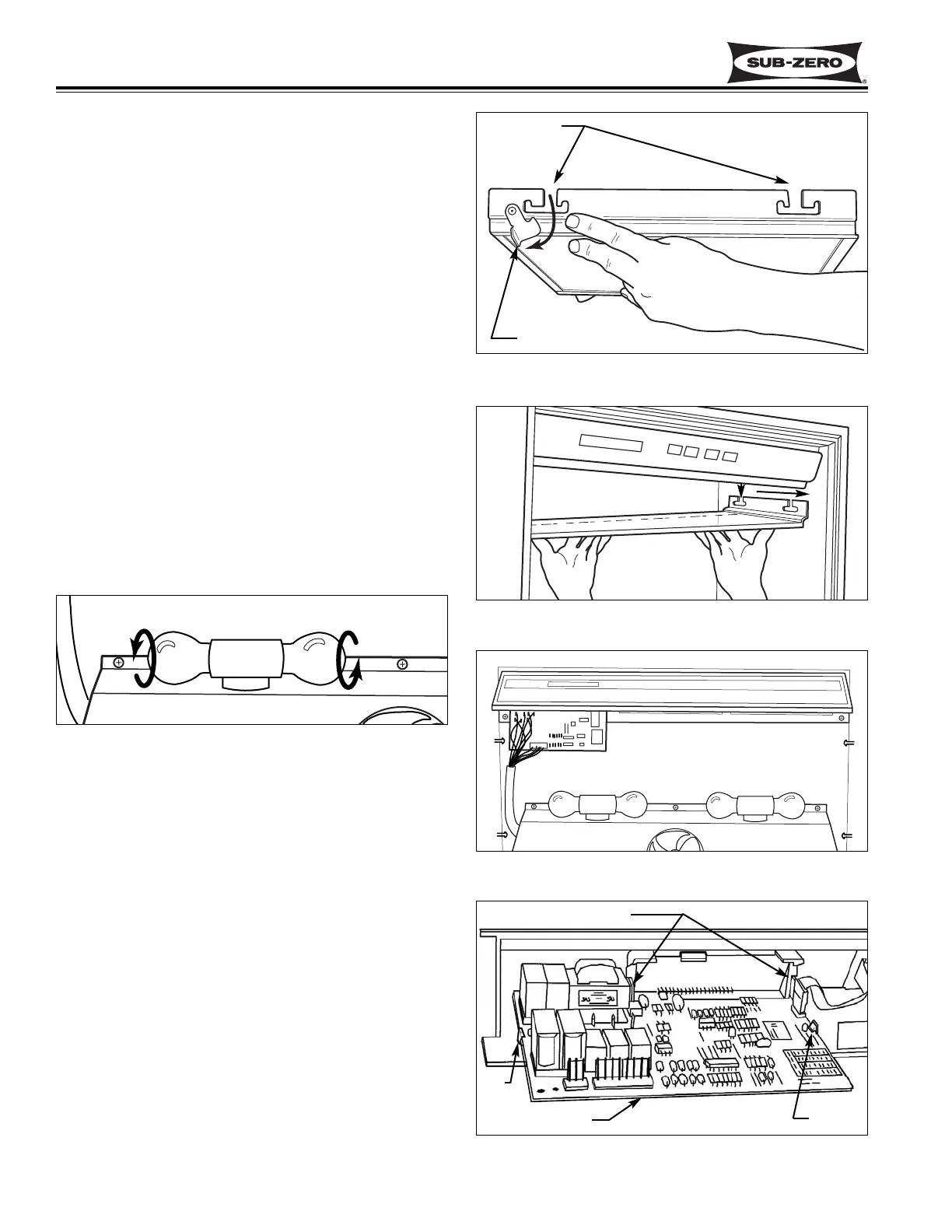
Upper Light Diffuser Removal (All Tall Units)
The side frames of the upper light diffuser have four
inverted “T” shaped slots (two each side) which fit over
pegs protruding from the side walls of the upper com-
partment. Retaining clips at the rear slots secure the
diffuser to the rear pegs.
To remove the light diffuser, slide a finger over the top
of each retainer clip flange and rotate the retainer clip
down and back. (See Figure 7-8) With the clips open,
lift the diffuser up and slide it towards the rear of the
unit until the center of the “T” slots line up with the
pegs. Then lower the diffuser down and pull forward
from the unit. (See Figure 7-9)
Light Bulb Removal (All Tall Units)
To access the upper light bulbs, the light diffuser must
be removed first. With the diffuser removed, screw the
bulb counterclockwise to remove it and clockwise to
install it. (See Figure 7-10)
The light bulbs in the drawer area are not covered by
light diffusers. Screw the bulb counterclockwise to
remove and clockwise to install. (See Figure 7-10)
Control Board Removal (All Tall Units)
The control board is held in position by two sets of tabs
behind the left side of the control panel. The two for-
ward tabs position the LCD in the control panel window,
while the other two tabs secure the middle of the control
board. The control board is then shielded by a control
enclosure and concealed by the light diffuser.
To access and remove the control board, first remove
the light diffuser. Then, extract the screws securing the
control enclosure to the ceiling of the compartment.
Lower the back of the enclosure while pulling it toward
the rear of the unit. Disconnect all electrical leads
attached to the control board. Expand the two tabs at
the middle of the control board outward while pulling the
back of the board down slightly. Then, expand the two
forward tabs outward that hold the LCD in position, and
pull the control board down and toward the rear of the
unit.(See Figures 7-11 & 7-12.)
Figure 7-8. Upper Light Diffuser Removal
Figure 7-9. Upper Light Diffuser Removal
Retaining Clip
“T” Slots
Figure 7-10. Light Bulb Removal
counterclockwise to remove
Figure 7-11. Control Board And Control Panel
Figure 7-12. Control Board Removal
Line-up Slots with Pegs
Tab
Tab
Forward Tabs
Control Board