Component Access/Removal
Integrated (
Integrated (
700-
700-
2) Series
2) Series
7-9
#3756780 - Revision D - July, 2005
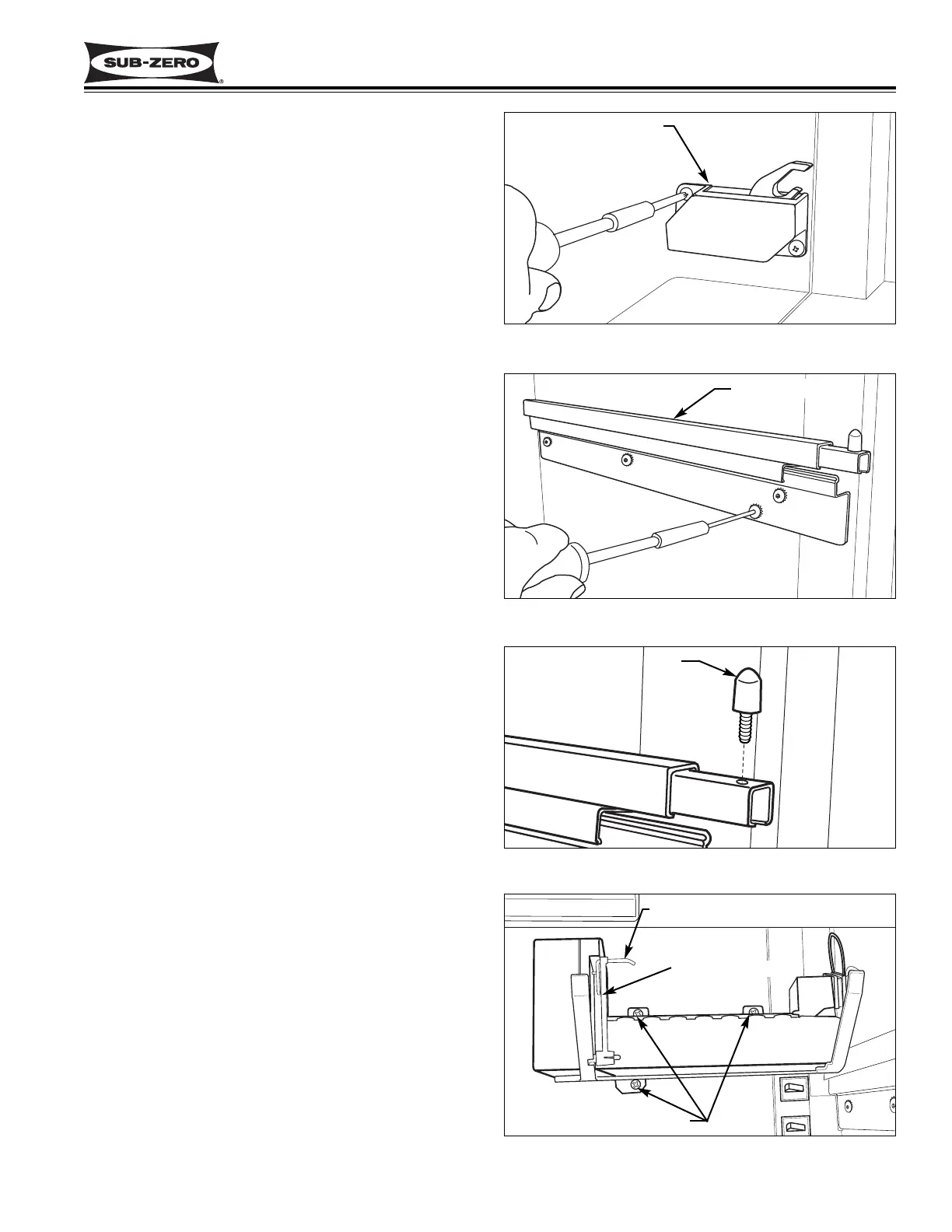
Drawer Closer Assembly Removal (All Tall Units)
The drawer closer assemblies are located on the right
side wall, towards the front of the two drawer areas.
Two screws secure each drawer closer to the wall.
To access and remove a drawer closer assembly, first
remove the appropriate drawer. Then, extract the two
screws that secure the drawer closer to the wall. (See
Figure 7-18)
Drawer Slide Assembly Removal (All Units)
There are four drawer slide assemblies in 700-2 Series
units, two on each side wall. The drawer slide assem-
blies are attached to the side walls with Allen-head
screws passing through the drawer slide bracket into
blind threaded inserts.
To access and remove a drawer slide assembly, first
remove the drawer. Then, extract the drawer slide
mounting screws with a 5/32" Allen-head wrench, and
pull the drawer slide assembly away from the wall.
(See Figure 7-19)
NOTE: The pins at the end of the drawer slides are
replaceable. Screw the pins counterclockwise to
remove them. (See Figure 7-20)
Icemaker Assembly Removal
(700TCI-2, 700TFI-2, 700TFI-2V)
The icemaker is attached to a support plate with three
screws that pass up through the plate into the bottom of
the icemaker. The ice level arm is also attached to the
support plate using two P-clamps and two screws. The
P-clamps fit around rods at the back of the ice level
arm. Screws passing through the P-clamps secure
them to the support plate at the rear. At the front, a
connecting rod is used to attach the ice level arm to the
icemaker shut-off arm. This whole assembly is
attached to the evaporator cover with three mounting
screws, two at the top and one at the bottom. (See
Figure 7-21)
To access and remove the icemaker assembly, first
remove the bottom drawer. Then, extract the bottom
icemaker mounting screw and the two top mounting
screws. (See Figure 7-21) Lower the icemaker assem-
bly down and disconnect the wire harness from the
back left of the icemaker.
The icemaker can now be removed from the support
plate by first sliding the connecting rod off of the shut-
off arm, then extracting the three screws from the bot-
tom of the icemaker.
Drawer Closer Assy
Figure 7-18. Drawer Closer Assembly Removal
Figure 7-19. Drawer Slide Assembly Removal
Drawer Slide Assy
Figure 7-20. Pin Replacement
Pin
Figure 7-21. Icemaker Assy, TCI-2, TFI-2, TFI-2V
Icemaker
Mounting Screw
Shut-off Arm
Connecting Rod