Planning Information
Model 700TC(I)
Dimensions in parentheses are in
millimeters unless otherwise specified.
13
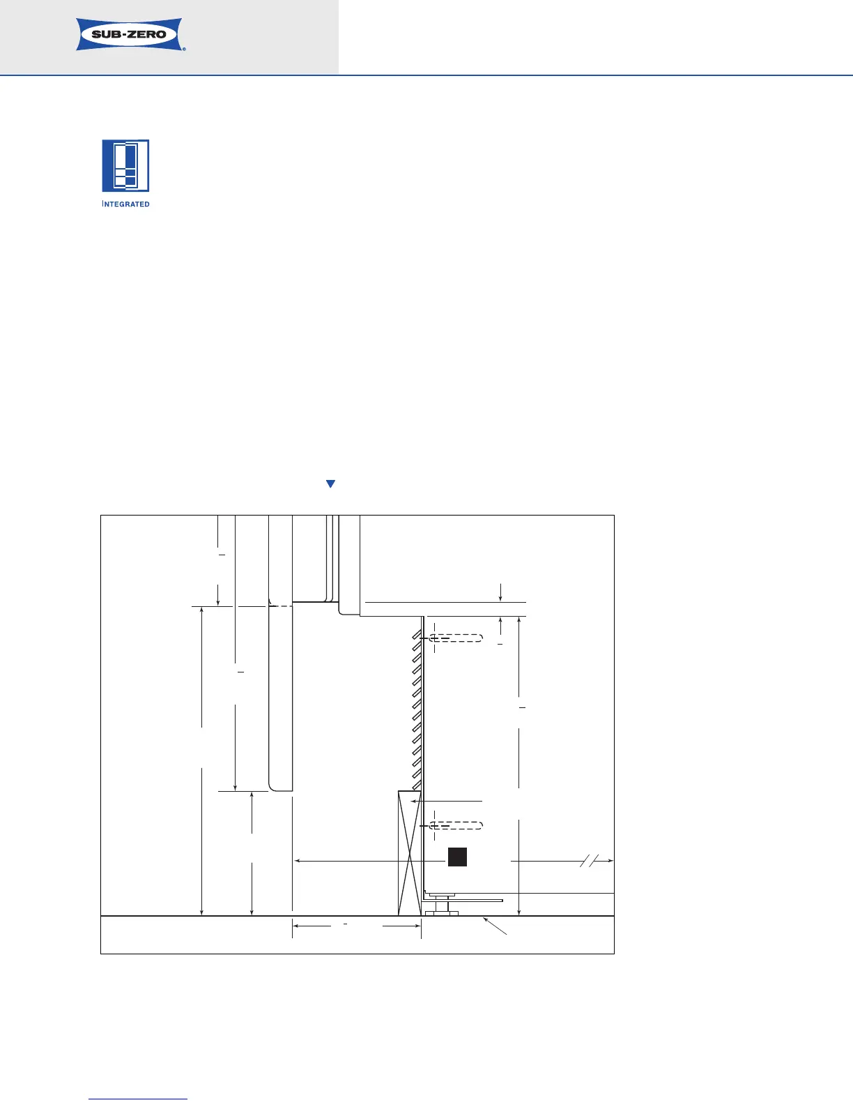
TOE KICK CLEARANCE
The toe kick clearance can vary with the height of the
lower drawer panel; the maximum panel height is 16
1
1
/1
6
"
(424).
IMPORTANT NOTE: You must keep a minimum space of
4" (102) clear below the bottom edge of the lower drawer
p
anel so the unit can be properly vented. In addition, any
decorative base molding must be removable for possible
servicing and cleaning of the condenser.
The illustration below shows the area below the lower
drawer where the operating mechanical equipment of the
Integrated unit is housed.
IMPORTANT NOTE: The depth of each Integrated unit is
24" (610) from the front of the unit to its back. Your
design may necessitate moving the unit back, or cabinets
forward to achieve a flush fit. This will require a minimum
rough opening depth of 25" (635). Refer to the illustration.
10
9
16
(268)
16
11
16
(424)
PANEL
PANEL
10
(254)
4
(102)
OPTIONAL
2
5
8
(67)
4
(102)
TO
9
11
16
(246)
1
2
(13)
FLOOR
TO WALL
24
(610)
BASE MOLDING MUST
BE REMOVABLE
TOE KICK AREA DETAIL