Site Preparation 10
An anti-tip bracket and hardware is provid ed with the inte-
grated unit. Placement of the anti-tip bracket i s critical to
a stable installation. The anti-tip bracket mu st be installed
on a solid base .
If you are installin g the unit in a space deeper than 24"
(610), be sure to locate the anti-tip bra cket so that it
engages the unit pro perly. It is important that the anti-tip
bracket is placed 24"
(610) from the front of the unit
(without panels) to the back of the anti-tip bracket.
IMPORTANT NOTE: In some installations the su bflooring
or finished floor may require an gling the wood screws
used to fasten the anti-tip bracket to the back wall.
WOOD FLOO R APPLICATIONS
Use the six #12 x 2
1
/2" wood screws and the six
1
/4" flat
washers provided. Drill pilot holes
3
/1
6
" (5) diame ter
maximum, and make sure the screw s penetrate through
the flooring material and into the wall plate a mini mum of
3
/4" (19). Make sure the screws hold tight. Refer to the
illustration below.
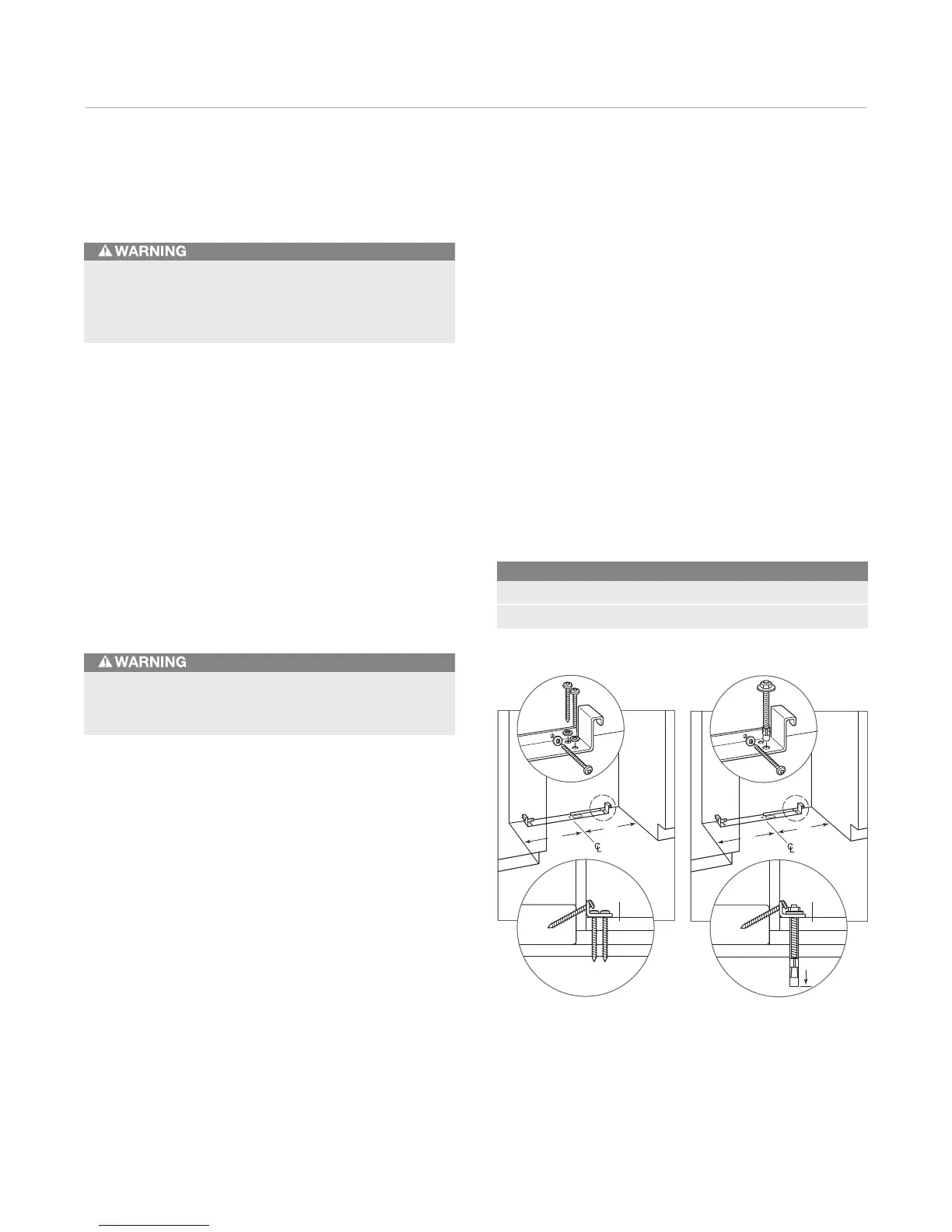
CONCRETE FLOOR APPLICATIONS
Use the two
3
/8" x 3
3
/4" concrete wedge anchors, two
#12 x 2
1
/2" wood screws and two
1
/4" flat washers
provided. Make sure the anchors an d screws hold tight.
Refer to the illustration below.
Anti- Tip Bracket Installation
Make sure there are no electrical wires or plumbing
in the area which the screws could penetrate.
To prevent the unit from tipping forward and provide
a stable installation, the unit must be secured in place
with the anti-tip bracket provided with the unit.
Ant i-Tip Bracket Placement A
27" (686) Models 13
1
/2" (343)
36" (914) Models 18" (457)
A
A
SUBFLOORING
WOOD FLOOR
WALL PLATE
FINISHED
FLOORING
A
A
SUBFLOORING
CONCRETE
FLOOR
WALL PLATE
FINISHED
FLOORING
1
1
/2"(38)
min
Wood floor. Concrete floo r.