Integ rated Installation 12
Posit ion the Unit
P
lug the power cord int o the gro unded electrical outlet.
With power applied to the appliance, check for lig hting
and cooling. Press t he UNIT ON/OFF key pad on the
control panel (POW ER for column models). Refer to the
illustrations below. Once you are satisfied that the unit is
operating proper ly, shu t off pow er to the electrical outlet at
the circuit breaker and proceed.
If two integrated units are installed closer than 2"
(51) to
one another, refer to dual installations o n page 20.
Pre-level the unit b efore m oving into position. This is to
allow the unit to engage the anti-tip bracket properly.
Slide the unit into position, making sure the anti-tip
bracket is engaged properly. E xtend the front leveling legs
down approximate ly
3
/16" (5) to m ake additional adjust-
ments easier.
When the integrated unit is installed, the anti- tip bracket
will be positioned just below the engaging brack et on the
unit. It is not necessary to raise the unit up so that it locks
into the anti-tip bracket, but the unit must be in alignment
with the anti-tip bracket.
The floor under the integrated unit must be at the same
level as the surroun ding finished floor to allow the com-
pressor tray to be sli d forward for service.
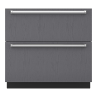
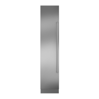
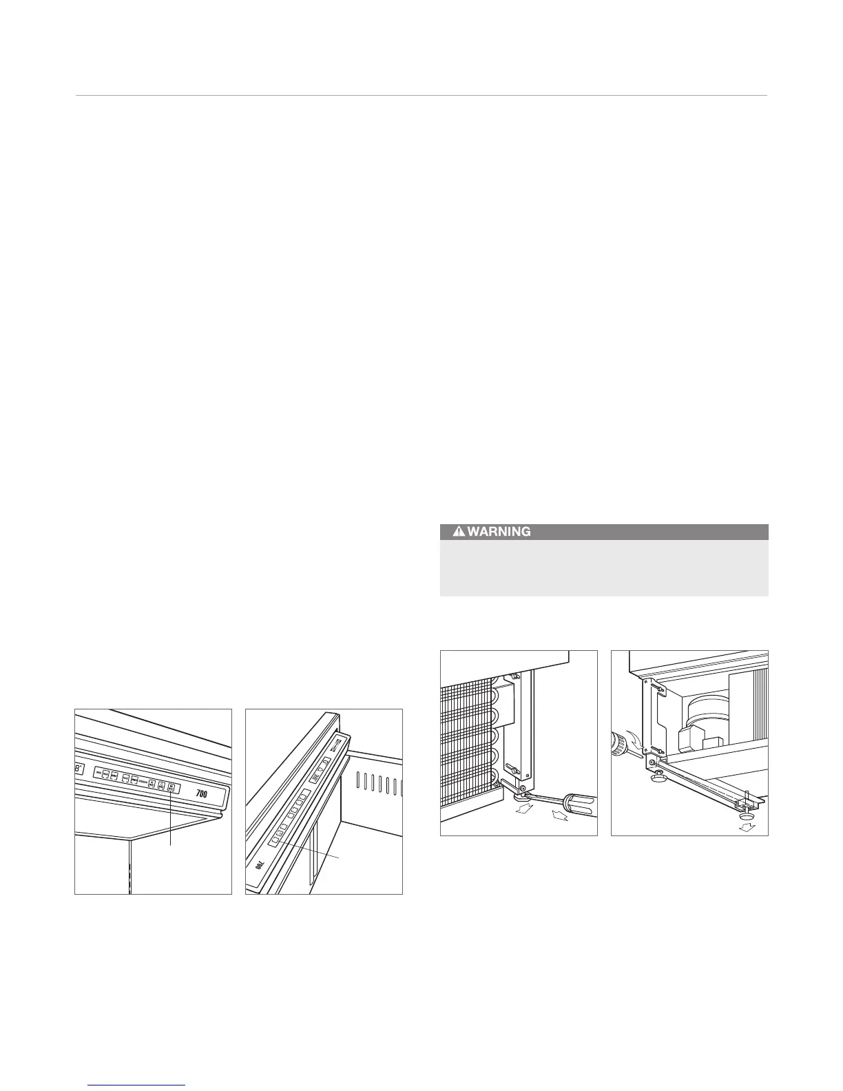
On/off key pad— tall model. On/off key pad— drawer model.
C
O
L
D
E
R
W
A
R
M
E
R
R
E
F
R
I
G
E
R
A
T
O
R
F
R
E
E
Z
E
R
C
O
L
D
E
R
W
A
R
M
E
R
I
C
E
O
N
/
O
F
F
O
N
/
O
F
F
U
N
I
T
O
N
/
O
F
F
UNIT
ON/OFF
Level the Unit
L
evel the integrated unit by turning the front leve ling legs
clockwise to raise or counterclockwise to lower the unit.
To assist you in adjusting the front leveling leg s up or
down, use a standard s crewd river blade and place it in the
front leveling leg a s shown in the illustration below.
The rear leveling le gs are ad justed from the fro nt of the
base by turning the Phillips head screw as shown in th e
illustration below.
IMPORTANT NOTE: The rear leveling legs will only move
1
/16" (2) fo r every 18 revolutions on the Phillips head sc rew.
Do not over torque. Us e the lowest torque setting on any
power screwdrive r. Do not turn the rear l eveling legs by
hand.
Once the unit is leveled, secure the unit in place by using
the side mounting clips and #8 x
1
/2" screws provided.
Front levelin g legs. Rear leveling legs.
To reduce the possibility of the unit tipping forward,
the front leveling legs must be in contact with the floor.