Electronic Control System
Under Counter (UC-24) Series
3-11
#7003933 - Revision B - November, 2007
FUNCTIONS OF ELECTRONIC CONTROL SYSTEM
The following few pages explain monitoring, regulating and controlling functions of the electronic control system.
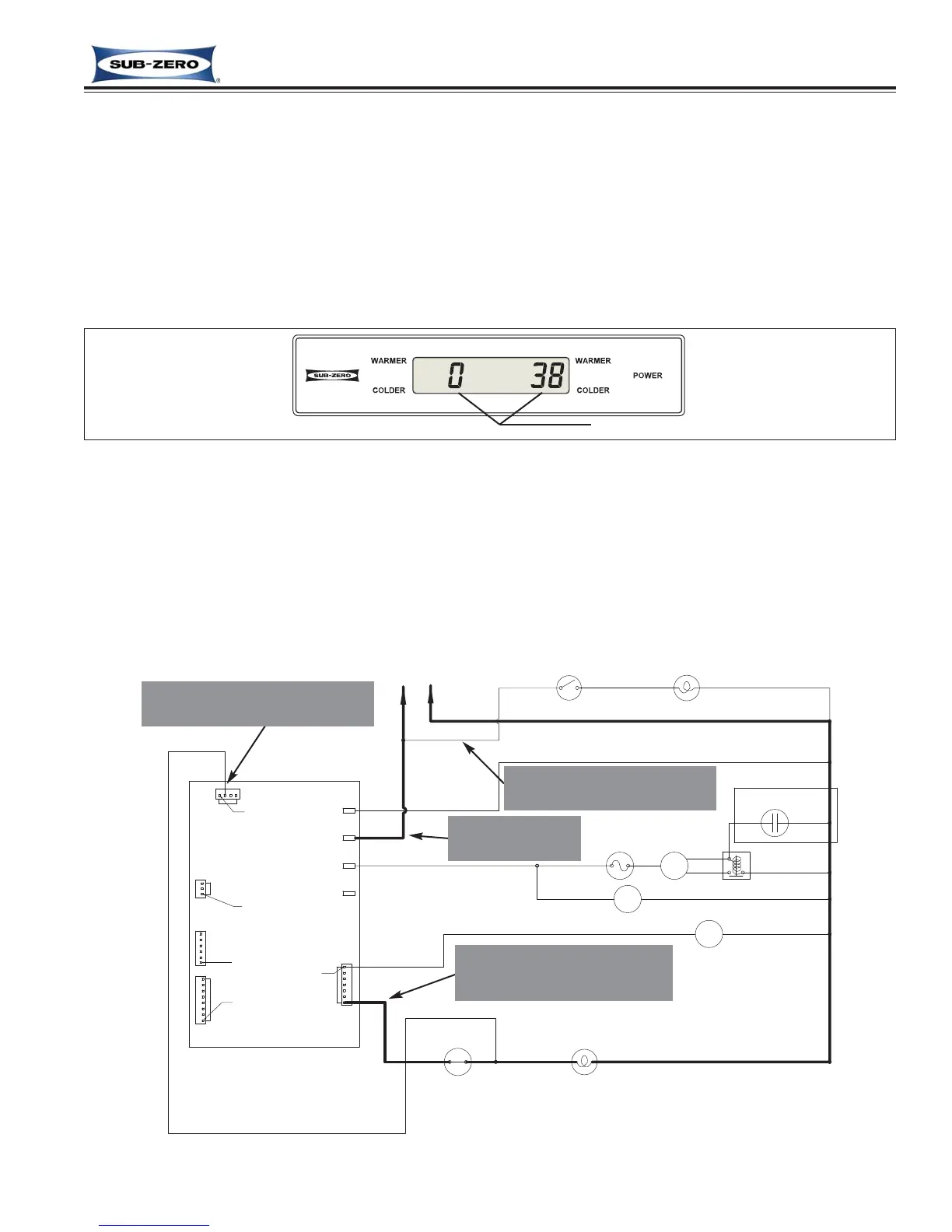
Display Zone Temperatures
The temperature signals from the thermistors in the refrigerator and freezer compartments are monitored by the
microprocessor and then displayed on the LCD. Though the compartment air temperature does fluctuate, the LCD
displays the “average” temperature (See Figure 3-16).
NOTE: If zone temperature changes, temperature display will change by one degree per minute.
Figure 3-16. Display Zone Temperatures
“average” temperature displayed
Figure 3-17. UC-24B Signal Trace Schematic (High Voltage) of Lighting System
RELAY
STARTING
(WHEN
USED)
CAPACITOR
COMPRESSOR
REF LIGHT
SWITCH
WHITE
BLACK
PROTECTOR
M
M
M
ORANGE
PURPLE
ORANGE
PIN 1
PIN 1
PIN 1
YELLOW
MAIN BOARD
PIN 1
ORANGE
PIN 1
WHITE
REF (TOP)
LIGHT
REF FAN MOTOR
OVERLOAD
CONDENSER FAN
RED
COMPRESSOR
RUNNING
WHITE
NEUTRAL
HIGH VOLTAGE SCHEMATIC
L1
115 VOLTS
60 CYCLES
LIGHTS
PINK
WHITE
REF LIGHT
SWITCH
LIGHT TUBE SWITCH
(UC-24B ONLY)
J4
J5
J3
J6
J2
P3
P2
P1
P4
Supply Power to the Lighting System
Power is supplied to the lighting system through the control board when the unit is switched ON by pressing the
POWER key. With the door open, the light switch allows power to the lights. (See Figure 3-17).
NOTES:
• Power to the lights is monitored by the microprocessor to control evaporator fan motor operation.
• When in Sabbath Mode, the lighting system is disabled. Sabbath Mode was covered earlier in this section.
• The accent lighting system in the model UC-24B is fed direct from L-1.
2. Power supplied to lighting sys-
tem unless unit is switched
OFF, or in Sabbath Mode.
NOTE: Light switch position
monitored to control fan operation.
1. Power supplied
to control board.
NOTE: Accent lighting system
in UC-24B is fed direct from L1.