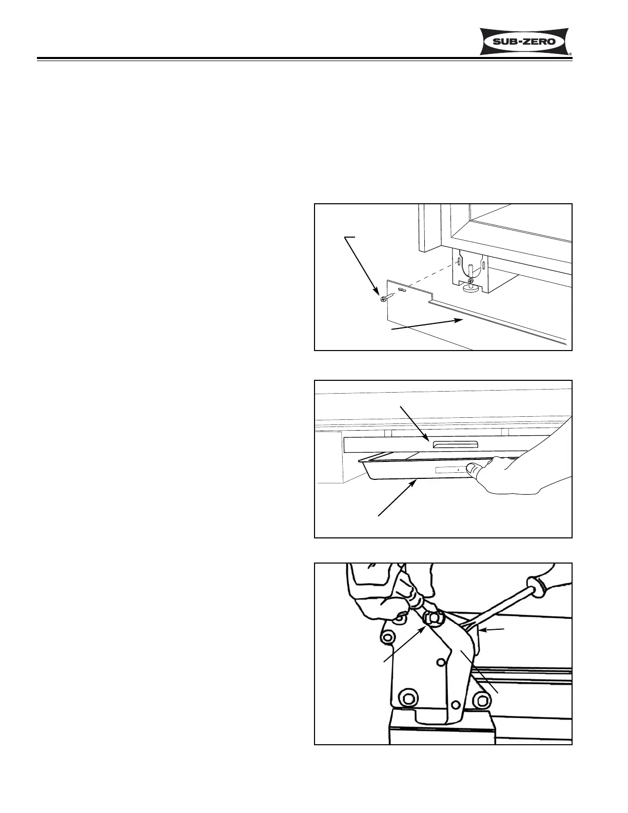
Figure 6-65. Drain Pan Removal
Figure 6-66. Door Closer Removal
Remove E-ring
Pry arm down
Door closer arm
400 Series
400 Series
Component Access and Removal
6-30
Kickplate Removal (Model 430)
To remove the kickplate, extract the mounting screws
located at each end of the kickplate and pull the kick-
plate forward. (See Figure 6-64)
Drain Pan Removal (Model 430)
To access and remove the drain pan, the kickplate must
first be removed. Now push the front of the drain pan
back and down. (This flexes the drain pan slightly,
releasing the top flange from the tab in the kickplate
support.) Then, pull the drain pan forward. (See Figure
6-65)
NOTE: When reinstalling, the tapered end of drain pan
must be inserted on top of the drain pan holder at rear.
Then push the front of the drain pan up until the front
flange engages the tab in the kickplate support. Also,
make sure the drain hoses are over the drain pan, and
the foam air seals which direct air over drain pan are in
position and in good shape.
Door Closer Removal (Model 430)
The door closer assembly sets inside of the unit base
and the door closer arm is held on the bottom door
hinge stud with an E-ring.
NOTE: The procedure for "disconnecting" the door clos-
er when removing a door is different than the door clos-
er "removal" procedure listed below. (See DOOR
CLOSER CAUTION at beginning of this section.)
With door closed, use a small straight-blade screwdriver
to remove the E-ring which holds the door closer arm to
the stud on the bottom door hinge. Then, pry the door
closer arm down off of the door hinge stud and pull the
door closer assembly from the front of the unit base.
(See Figure 6-66)
Figure 6-64. Kickplate Removal
Kickplate
Screw
Drain Pan
Kickplate Support
MODEL 430
MODEL 430 EXTERIOR COSMETIC AND MECHANICAL COMPONENT REMOVAL:
An attempt has been made to arrange these instructions in such a way as to simulate which components would
need to be removed first in order to gain access to other components. When following a component removal proce-
dure, it may be necessary to reference another removal procedure towards the front of this section.