400 Series
400 Series
Component Access and Removal
6-4
Door Removal (Model 424)
To remove the door you will need to pull the unit
approximately 6" out of the rough-in opening and
remove the door closer first. (See TIPPING WARNING
at beginning of this section)
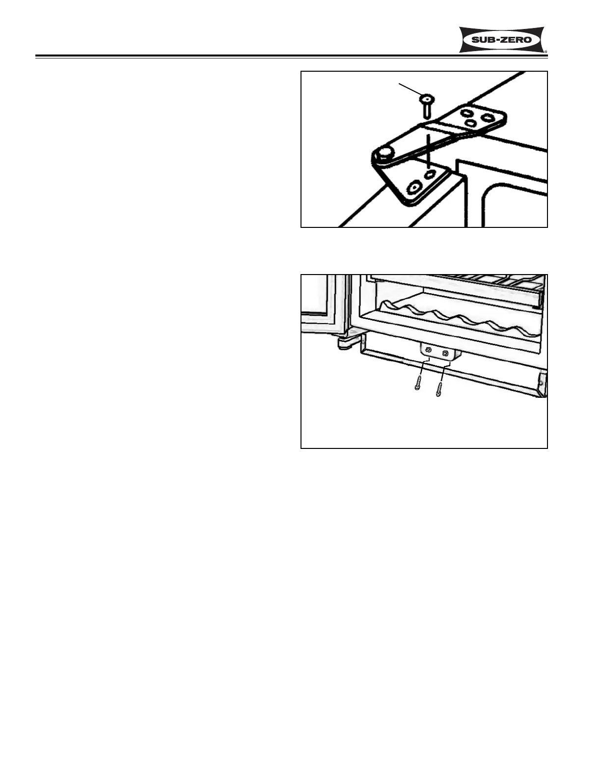
NOTE: If removing a model 424 from its installation, an
anti-tip bracket and a countertop bracket may have
been used to make a solid installation. (See Figures 2-
2) If the brackets were not used, shims may have been
wedged along the sides and top.
After removing the door closer, open the door and
extract the two screws from the top door hinge. (See
figure 6-3) Lean the door away from the unit slightly
and lift the door out of the bottom cabinet hinge.
Light and Fan Switch access and Removal
(Model 424)
The light and fan switches are attached to a switch
bracket, and covered by a switch guard. The switch
bracket and guard are held in place by two Phillips
head screws that pass up through holes in the switch
bracket and slots in the switch guard on the backside.
NOTE: See ELECTRIC SHOCK WARNING at begin-
ning of this section.
To access and remove a fan or light switch, extract the
two phillips head screws on the backside of the switch
bracket, using an offset Phillips screwdriver. (See
Figure 6-4) Pull the switch guard and bracket forward.
Disconnect the electrical leads from the switch being
removed. Depress the tabs on the side of the switch
being removed and push the switch out of the bracket.
Figure 6-3. Top Door Hinge
Figure 6-4. Light and Fan Switch
Door Hinge Screw
Use 90° offset Phillips-head
screwdriver to reach screws