MAKING ELECTRICAL CONNECTIONS
12 VOLTS D.C.
A. Applicable to following models: SW10D, SW10DE, SW10DM, SW10DEM
SW12D, SW12DE, SW12DEM, SW16D, SW16DE, and SW16DEM.
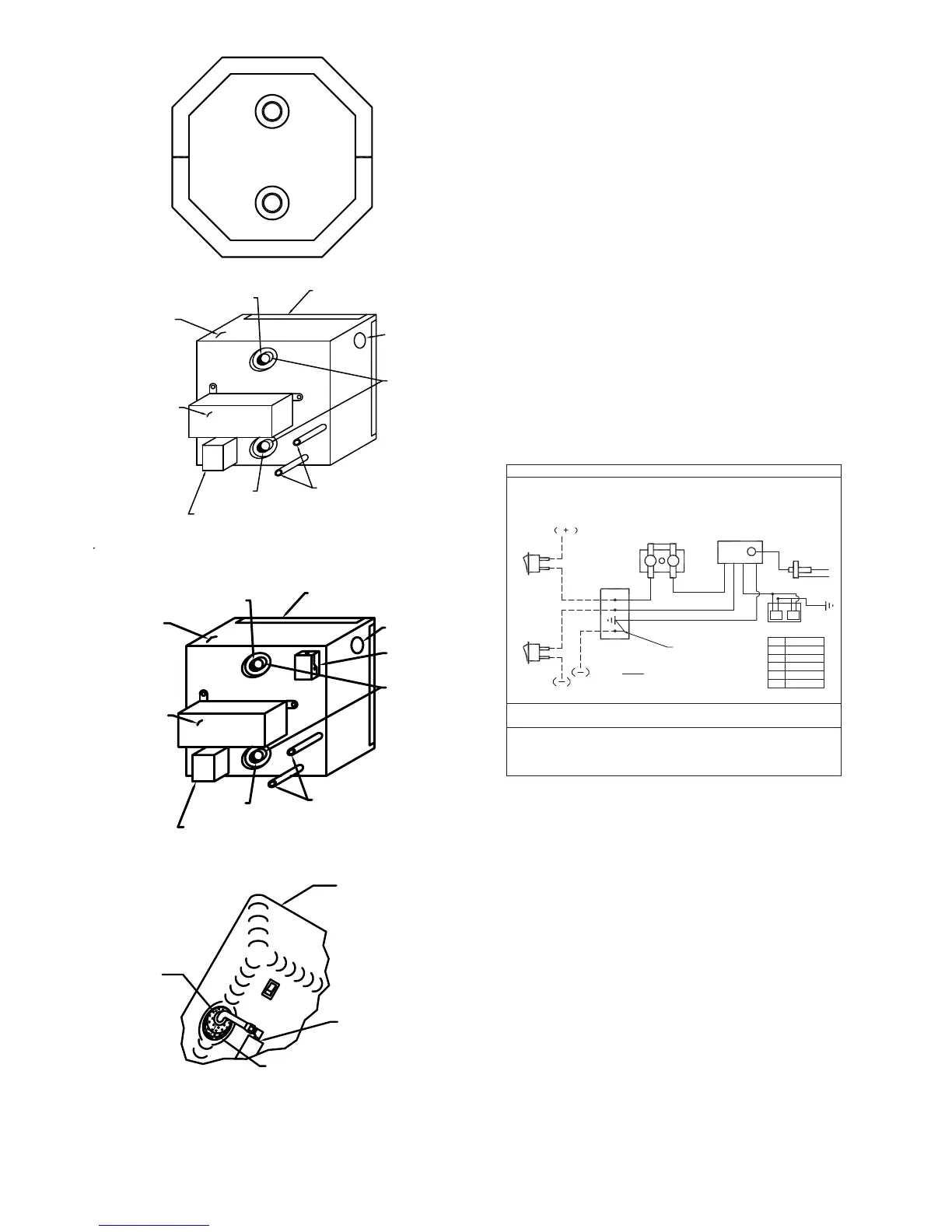
B. Refer to Figure 2 for location of D.C. junction box on models SW10D
,SW10DE SW12D, SW12DE, SW16D and SW16DE. Refer to Figure 4 and 5 for
location of D.C. junction box on models SW10DM, SW10DEM, SW12DEM and
SW16DEM.
C. The electrical connections must be made in accordance with local codes and
regulations. In the absence of local codes and regulations, refer to the latest
edition of the National Electrical Code NFPA No. 70.
In Canada, the electrical installation should conform with CSA standard Z240.6.2-
08/C22.2 No. 148-08 Electrical Requirements for Recreational Vehicles and CSA
C22.1 Canadian Electrical Code Part 1 when installing the unit in recreational
vehicles and mobile homes respectively.
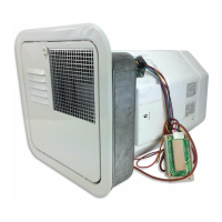
D. Make the 12 Volt D.C. electrical connections following the wiring diagram
illustrated in Figure 7.
If the power supply is to be from a convertor, we recommend that the converter
system be wired in parallel with the battery. This will serve two purposes:
1. Provide a constant voltage supply
2. Filter any A.C. spikes or volt surges
We recommend insulated terminals be used for all electrical connections.
MAKING ELECTRICAL CONNECTIONS
120 VOLTS A.C.
A. Applicable to following models SW10DE, SW10DEM, SW12DE, SW12DEM,
SW16DE, SW16DEM.
B. Refer to Figure 2 for location of A.C. junction box on models SW10DE,
SW12DE or SW16DE. Refer to Figure 5 for A.C. junction box on model SW10DM,
SW10DEM, SW12DEM or SW16DEM.
C. The electrical connections must be made in accordance with local codes and
regulations. In the absence of local codes and regulations, refer to the latest
edition of the National Electrical Code NFPA No. 70.
In Canada, the electrical installation should conform with CSA standard Z240.6.2-
08/C22.2 No. 148-08 Electrical requirements for Recreational Vehicles and CSA
C22.1 Canadian Electrical Code Part 1 when installing the unit in recreational
vehicles and mobile homes respectively.
D. Check rating plate and wiring diagram (Figure 8) before proceeding. Install a
fused safety switch or circuit breaker of adequate capacity between heater and
electrical power source. Attach the black and white wires from the fused switch
or breaker to corresponding colored wires in heater junction box. A green wire
from a well grounded source must be attached to the green nut in the junction
box.
Figure 3
ACCESS MODULE
BOARD
JUNCTION BOX
COLD
MOTOR AID
1/2 FEMALE
PIPE FITTING
ACCESS HOLE
GAS SUPPLY
CONTROL HOUSING
HOT
JACKET
JUNCTION BOX
120 V.A.C.
Figure 5
CAULK AND SEAL GROMMET (INCLUDING SLIT
AND TUBING) ALL AROUND AIR TIGHT
GAS VALVE
ILLUSTRATED SHOWING
INSIDE OF HOUSING
GROMMET
(GAS INLET)
CALFATER ET ÉTANCHÉIER LA BAGUE (Y
COMPRIS LA FENTE ET LA COLONNE DE
LE TUBE À GAZ
LA BOÎTE DE COMMANDE
ILLUSTRÉE, MONTRANT
L'INTÉRIEUR DE LA BOÎTE
LA BAGUE
(L'ADMISSION
DE GAZ)
PRODUCTION)
O
N
O
F
F
Figure 6
ACCESS MODULE
BOARD
JUNCTION BOX
12 V.D.C.
COLD
MOTOR AID
1/2 FEMALE
PIPE FITTING
ACCESS HOLE
GAS SUPPLY
CONTROL HOUSING
HOT
JACKET
Figure 4
12 V.D.C. ONLY
JUNCTION
BOX
Y
G
BL
R
RED
BLUE
GREEN
YELLOW
BROWN
BR
BK
BLACK
G
BL
R
R
Y
BK
1
2
3
4
IF ANY OF THE ORIGINAL WIRE AS SUPPLIED WITH THE WATER
HEATER MUST BE REPLACED, IT MUST BE REPLACED WITH 18 GA.,
105°C WIRE OR IT'S EQUIVALENT.
SWITCH
HI-LIMIT T'STAT
MODULE BD.
SPARK CABLE
ELECTRODE
BR
GAS VALVE
LIGHT
( FACTORY WIRING)
( ---- FIELD WIRING)
DISCONNECT POWER SUPPLY BEFORE SERVICING THERMOSTAT
AND HI-LIMIT UNDER ACCESS COVER.
1 3 4 6
CAUTION: DO NOT HI-POT (DIELECTIC HIGH VOLTAGE TEST) THIS
UNIT AFTER INSTALLATION. TO DO SO MAY CAUSE COMPONENT
DAMAGE AND VOIDS WARRANTY OF WATER HEATER.
340461
Figure 7
4