2-7
#7013455 - Revision A - April, 2009
Installation Information
International W
International W
ine Storage
ine Storage
(ICBWS)
(ICBWS)
Series
Series
Door Adjustments
The doors on the model WS-30 can be adjusted in
three ways: up and down, side to side, and in and out.
IMPORTANT NOTE: Door adjustments must be per-
formed after the unit is installed and properly leveled.
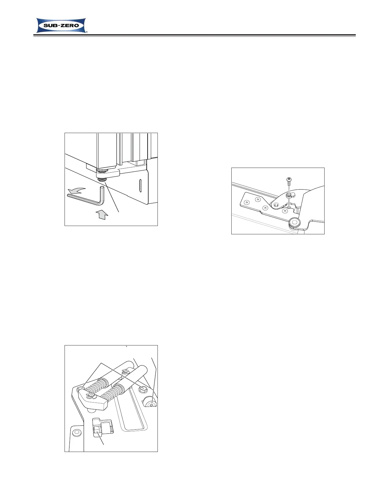
Door Height Adjustment Procedure:
Using a 1/4" allen wrench, turn the bottom hinge
adjuster bolt clockwise to raise the door and counter-
clockwise to lower the door. (See Figure 2-6)
Figure 2-6
Side to Side and In and Out Adjustment Procedure:
IMPORTANT NOTE: Side to side and in and out
adjustments only affect the top of the door. The bottom
hinge is stationary, except for height adjustments.
1. Loosen the two upper cabinet hinge mounting bolts
using a 1/2" wrench (See Figure 2-7).
2. For side to side adjustments, use a 3/8" open-end
wrench to turn bolt mounted left to right in top hinge
assembly in appropriate direction (See Figure 2-7).
3. For in and out adjustments, use a 5/32" allen
wrench to turn bolt mounted front to back in top
hinge assembly in appropriate direction (See Figure
90-Degree Door Stop
The door on the model WS-30 opens to 110-degrees.
An optional 90-degree door stop kit is supplied with the
unit, and is also available through a Sub-Zero dealer or
distributor.
The 90-degree door stop will be installed in the top
hinge of the door.
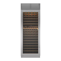
Door Stop Installation Procedure:
1. Open door to approximately 90 degrees.
2. At top of door, insert door stop cam down
between door hinge and door closer arm as
shown in Figure 2-8.
3. Insert screw through door stop and into door as
shown in Figure 2-8.
Figure 2-8. 90 Degree Door Stop