4-4
#7013455 - Revision A - April, 2009
Sealed System Information
International W
International W
ine Storage
ine Storage
(ICBWS)
(ICBWS)
Series
Series
WINE STORAGE SEALED SYSTEM
The following six diagrams illustrate a basic wine stor-
age sealed system. The components are listed in order
of refrigerant flow, with an explanation of their funda-
mental role as part of a sealed system.
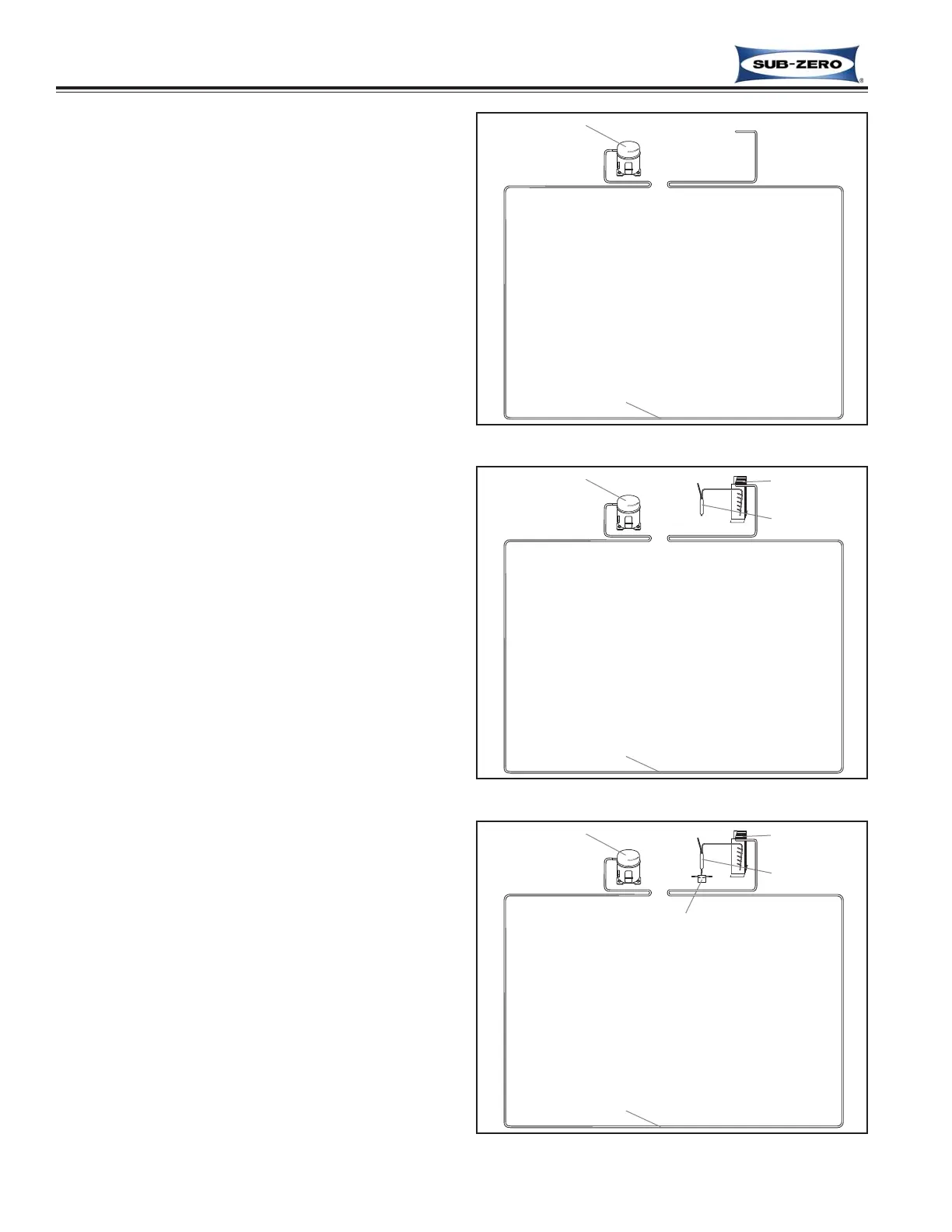
Compressor (Figure 4-1)
The compressor creates a high and low side pressure
difference in the sealed system. When the compressor
piston pushes, compressing the refrigerant gas, it caus-
ing the refrigerant pressure and temperature to rise
(high side pressure), while behind the piston, a vacuum
force is created (low side pressure).
The high-pressure/high-heat refrigerant gas is pushed
out the compressor discharge tube and through the
frame heater/hot gas tubing, routed around the door
gasket seat frame to prevent sweating. (On the model
WS-30, this hot gas also travels through tubing by the
drain pan to help evaporate water in the drain pan.)
The high-pressure/high-heat gas then enters the con-
denser.
Condenser (Figure 4-2)
The high-pressure/high-heat gas travels through the
condenser tubing, where most of the heat in the refrig-
erant is drawn out and dissipated into the room by the
cooler ambient air that is being drawn over the con-
denser tubing (referred to as heat transfer). This
changes the gas into a high-pressure warm liquid
before it enters the high-side filter-drier.
Filter-Drier (Figure 4-2)
The high-pressure warm liquid travels through the high-
side filter-drier, where the desiccant pellets inside the
drier remove moisture from the refrigerant before it
enters the dual refrigerant valve.
Dual Refrigerant Valve (Figure 4-3)
The tubing that is part of the dual refrigerant valve is a
T-connection with a bead inside. This bead is forced to
one side of the T-connection, or the other, depending
on the electrical signal from the control board to the
valve solenoid. When the bead is to one side of the T-
connection, that side is closed, the other side is open.
The open side of the dual refrigerant valve T-connection
allows the high-pressure warm liquid to enter the appro-
priate capillary tube.
Figure 4-1. Compressor
Figure 4-2. Condenser & Filter-Drier
Figure 4-3. Refrigerant Valve(s)