EasyManua.ls Logo

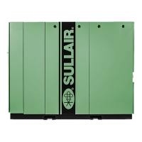
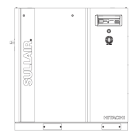
Sullair SN75 - User Manual

Sullair SN75
80 pages
To Next Page IconTo Next Page
Loading...
PART NUMBER:
02250247-571 R04
The information in this manual is current as of its
publication date and applies to compressor models
indicated on this cover with serial number:
201903080000
and all subsequent serial numbers until next revision of
this manual or release of a replacement manual..
Publication date: 03/27/2020
Copyright © 2020 Sullair, LLC. All rights reserved.
WARRANTY NOTICE
Failure to follow the instructions
and procedures in this manual,
or misuse of this equipment, will
void its warranty.
Subject to EAR, ECCN EAR99 and related export control restrictions.
SAFETY WARNING
Users are required to read the
entire User Manual before han-
dling or using the product. Keep
the User Manual in a safe place
for future reference.
USER MANUAL
Industrial Air Compressor
SN55, SN55S, SN55V,
SN75, SN75S, SN75V
75 & 100 hp (55 & 75 kW)

Table of Contents

Question and Answer IconNeed help?

Do you have a question about the Sullair SN75 and is the answer not in the manual?

Sullair SN75 Specifications

General IconGeneral
BrandSullair
ModelSN75
CategoryAir Compressor
LanguageEnglish

Summary

Industrial Air Compressor

SN55, SN55 S, SN55 V, SN75, SN75 S, SN75 V

Specifies the models covered by this manual.

75 & 100 hp (55 & 75 kW)

Indicates the power range of the compressors.

Section 1: Safety

Personal Protective Equipment

Requirements for eye, respiratory, and hearing protection.

Fire and Explosion Prevention

Precautions to prevent fire and explosion hazards.

Moving Parts Safety

Warnings about keeping clear of moving components.

Electrical Shock Prevention

Procedures to prevent electrical shock hazards.

Lockout;Tagout Procedures

Detailed procedure for energy control and lockout/tagout.

Variable Speed Drive (VSD) Safety

Specific warnings for VSD operations and electrical hazards.

Section 2: Description

Cooling and Lubrication System Function

How the cooling and lubrication system works.

Control System Function

How the control system regulates air output.

Variable Speed Drive (VSD) Components

Components of the Variable Speed Drive system.

VSD Control System Function

Operation of the VSD control system for variable output.

Section 3: Specifications

SN55, SN55 S, SN75, SN75 S Specification Table

Key dimensional and power specifications for SN55/SN75 series.

SN55 V, SN75 V Specification Table

Key dimensional and power specifications for SN55V/SN75V series.

Compressor Unit Specifications

Detailed specifications for the compressor unit itself.

Motor Specifications

Detailed specifications for the compressor motors.

Lubrication Change Recommendations

Schedule for fluid and filter changes.

Air-Cooled Piping & Instrumentation (SN55, SN75)

P&ID for air-cooled SN55/SN75 models.

Water-Cooled Piping & Instrumentation (SN55, SN75)

P&ID for water-cooled SN55/SN75 models.

Air-Cooled Piping & Instrumentation (SN55 S, SN75 S)

P&ID for air-cooled SN55S/SN75S models.

Water-Cooled Piping & Instrumentation (SN55 S, SN75 S)

P&ID for water-cooled SN55S/SN75S models.

Air-Cooled Piping & Instrumentation (SN55 V, SN75 V)

P&ID for air-cooled SN55V/SN75V models.

Wye-Delta Wiring Diagram

Electrical wiring diagram for wye-delta configurations.

VSD Air-Cooled Wiring Diagram

Electrical wiring diagram for VSD air-cooled systems.

Section 4: Installation

Section 5: Controller

Section 6: Maintenance

Troubleshooting Guide

Table of symptoms, probable causes, and remedies.

Related product manuals