EasyManua.ls Logo

Sumitomo Drive Technologies HYPONIC DRIVE - Page 25

Sumitomo Drive Technologies HYPONIC DRIVE
56 pages
Print Icon
To Next Page IconTo Next Page
To Previous Page IconTo Previous Page
Loading...
24
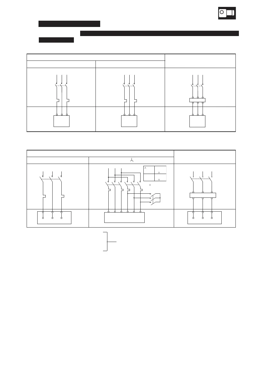
Fig.28-a In a case of three lead wires
Fig.28-b In a case of six lead wires
6–5) Motor (without brake) Connection
Fig.28 shows the 3-phase motor, 3-phase high efficiency motor, 3-phase inverter motor
(without brake)
connection and the standard specifications for terminal codes.
MC: Electromagnetic contactor
OLR: Overload relay or thermal relay
These should be furnished by the customer.
VR: Varistor (protector element)
· This drawing shows for a motor based on standard specification for domestic market.
Motor based on overseas standard shall be referred to us.
· Refer to connection diagram on the motor when sharing power supply.
15
90W
3-phase motor, 3-phase high efficiency motor
0.1
7.5kW
3-phase inverter motor
3-phaseinvertermotor7.5kW
Motor
RST
MC
OLR
WhiteRed Black
Motor
MC
OLR
VUW
RST
Motor
MCB
Inverter
VUW
RST
DirectStarting
Star (Wye)-Delta (
―△)Connection
3-phasemotor11kW
MC
OLR
RST
U1
V2
V1
W
2
W
1
U2
Motor
RST
MC
MCM
MC
OLROLR
1U 1V 1W U2 W2 V2
Y
Motor
MCM ON
MC△ OFF
MC ON
MCM ON
MC△ ON
MC OFF
connection
forstarting
connection
afterstart
MCB
Inverter
RST
U1
V2
V1
W2
W1
U2
Motor
Control panel
Terminal box
Control panel
Terminal box
Control panel
Terminal box
Control panel
Terminal
box
Control panel
Terminal
box
Control panel
Terminal
box
6. Wiring