12
5-3) Coupling hollow shaft type with other machines
(1) Attachment and Removal of Hollow shaft and Driven Shaft
(a) Attachment to Driven Shaft
Apply molybdenum disulfide grease to the surface of driven shaft and inner diameter of hollow shaft. Insert the
gearmotor or reducer to driven shaft.
Pound the end surface of hollow shaft lightly with a wooden hammer when the fitting is tight.
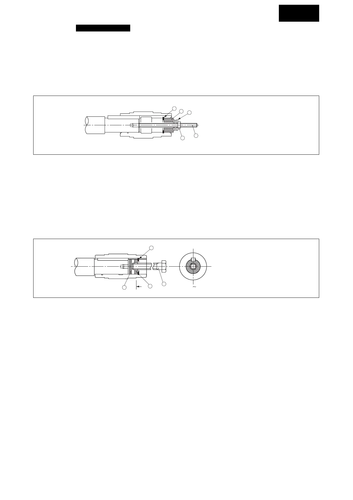
Do not pound casing and oil seal for this purpose. Jigs as shown in Fig. 8 can help smooth insertion when the fitting is
especially tight.
e
c
b
a
d
(a) .......... Retaining ring
(b) .......... Spacer
(c) .......... Thrust bearing
(d) .......... Nut
(e) .......... Bolt
Fig.8 Coupling jig
Hollow shaft conforms to JIS H8.
Make the fitting between hollow shaft and driven shaft when there is shock load or when the radial load is large. (js6 or
k6 of JIS standard is recommended for driven shaft.)
(b) Uncoupling from driven shaft
Make sure there is no excess force between casing and hollow shaft. Jig as shown in Fig. 9 can help smooth removal.
Prepare jig and parts for attachment, fixing, and removal by yourself.
g
h
A
i
f
A
(f) ............Spacer
(g) .......... Upper bolt
(h) .......... Disc
(i) ........... Retaining ring
Fig.9 Uncoupling jig
COMMON
 Loading...


