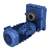
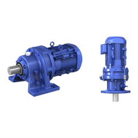
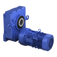
Do you have a question about the Sumitomo Cyclo BBB4 and is the answer not in the manual?
Identifies safety symbols used throughout the manual to indicate important warnings.
Provides essential safety guidelines for trouble-free operation and warranty claims.
Guidance on the proper disposal of unit components and materials.
Instructions for inspecting the unit upon arrival to check for damage and verify order.
Details required information from the nameplate for inquiries or service.
Checks required for oil-lubricated units before initial operation.
Defines the orientation of the output shaft for delivered units.
Describes different mounting configurations available for the unit.
Details the types of input connections for gearmotors and reducers.
Lists available frame sizes for single and double reduction units.
Information on shaft types and their corresponding specifications.
Specifies motor power ratings and their corresponding symbols.
Details the AGMA classes for gearmotor specifications.
Indicates the availability of a brake for gearmotor units.
Specifies output shaft direction options for shafted models.
Provides tables of nominal and exact reduction ratios for various configurations.
Lists specifications and suffixes for gearmotor configurations.
Lists specifications and suffixes for reducer configurations.
Illustrates and defines various mounting positions for the unit.
Guidelines for selecting an appropriate storage location for the unit.
Recommendations for storing the unit for extended periods.
Procedures to follow before operating a unit after it has been stored.
Safety precautions and methods for transporting the unit.
Critical safety and operational precautions before installing the unit.
Environmental conditions and location requirements for unit installation.
Guidance on mounting the unit in the specified position.
Recommendations for severe loading conditions, such as bolt grade.
Instructions for coupling the reducer/gearmotor to the driven machine.
Detailed instructions for installing the Taper-Grip® bushing system.
Steps for installing the unit with a keyed hollow bore shaft.
Instructions for mounting the unit using a Shrink Disc type hollow bore.
Explains the function of a torque arm in preventing shaft rotation.
Installation procedure for the turnbuckle type torque arm.
Installation procedure for the tie rod type torque arm.
Installation of the banjo type torque arm assembly.
Installation procedure for the T-Type torque arm.
Steps for removing the unit when equipped with a Taper-Grip® bushing.
Procedure for removing the unit with a keyed hollow bore.
Instructions for removing the unit with a shrink disc.
Maintenance procedure for the taconite seal lubrication system.
General information on unit lubrication and factory fill status.
How to interpret unit nameplate for lubrication details.
Determining the correct lubrication method based on unit configuration.
Lists approved oils and greases for bevel gear and Cyclo® portions.
Approximate oil quantities required for single and double reduction units.
Step-by-step guide for supplying oil to the unit.
Procedure for draining and disposing of used oil.
Approximate grease quantities for Cyclo® portion lubrication.
Procedure for adding and draining grease in lubrication models.
Guidelines for replacing grease in units.
Detailed steps for filling the bevel gear and Cyclo® portions with oil.
Procedure for draining oil from the unit, including plug sizes and torque.
General guidelines for wiring Sumitomo motors and brakemotors.
Procedure for checking motor insulation resistance.
Recommendations for protecting the motor against electrical faults.
Wiring methods for standard U.S. motors, including WYE/DELTA connections.
Wiring configurations for CE certified motors.
Details on wiring the brake system, including varistor selection.
Guidance for selecting the appropriate varistor for brake wiring.
Wiring diagrams for U.S. and CSA approved motor brake systems.
Wiring diagrams for CE motor brake systems, covering various voltage configurations.
Part numbers and specifications for brake rectifiers and power modules.
Illustrated breakdown of Cyclo® BBB4 reducer components with part numbers.
Part numbers for Cyclo® planetary reduction components (Ratios 11-18:1).
List of bearings and oil seals used in Cyclo® BBB4 reducers.
Information on bevel gearing sets, ratios, and tooth counts.
Overview of screw conveyor components and general assembly.
Step-by-step guide for assembling screw conveyor shafts and adapters.
General procedure for disassembling the Cyclo® portion of the unit.
Detailed steps for the general disassembly of the Cyclo® portion.
Detailed steps for the general reassembly of the Cyclo® portion.
Guide to identifying and resolving common reducer problems.
Guide to identifying and resolving common motor problems.
