4
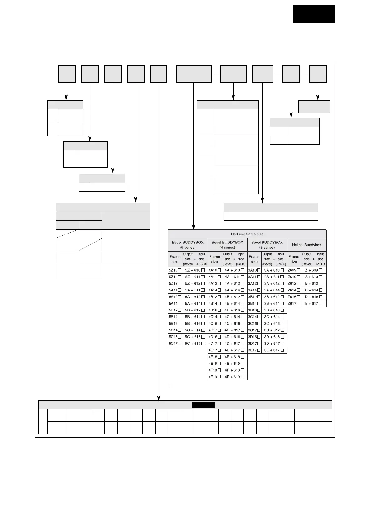
1-3) Inspection of Nomenclature of Gearmotor or Reducer
Nomenclature shows following information. Make sure it agrees with your order.
LM104
C
145 AV B 46
Model
L
E
Bevel
Buddybox
Helical
Buddybox
Mounting style
Y Hollow shaft
Coupling method with driver
Motor
Without With
M
Type of input
Gearmotor
Blank
Reducer
(Both - end shaft type)
Nominal
reduction ratio
Brake
B With brake
Blank Without brake
Mounting position
Refer to Table 1 and Table 2 on page 5-6.
Motor capacity of gearmotor
4 - pole
Capacity
Symbol
01 02
kW
(HP)
0.1
(1/8)
0.2
(1/4)
03
0.25
(1/3)
05
0.4
(1/2)
08
0.55
(3/4)
1
0.75
(1)
1H
1.1
(1.5)
2
1.5
(2)
3
2.2
(3)
4
3.0
(4)
5
3.7
(5)
8
5.5
(7.5)
10
7.5
(10)
15
11
(15)
20
15
(15)
25
18.5
(25)
30
22
(30)
40
30
(40)
50
37
(50)
60
45
(60)
75
55
(75)
JJM
With input flange
(With coupling base)
XXM
With input flange
(High - speed shaft
hollow coupling)
HY Y1
Output shaft direction
H Horizontal
V Vertical
indicates 0 or 5, depending on the combination of reduction ratio.
COMMON
Suffix
AV
With 3-phase motor
for inverter-drive
(AF motor)
SV With servo motor
ES
With high-efficiency
3-phase motor
TL With Torque limiter
EP
With premium efficiency
3-phase motor
AP
With premium efficiency
3-phase motor for
inverter-drive
Blank With 3-phase motor
 Loading...


