12 Hyponic® Operating and Maintenance Manual
Hyponic® Operating and Maintenance Manual 13
www.SumitomoDrive.com
4
Set the (untightened) shrink disc on the reducer shaft.
5
After confirming the correct position of the hub and shrink discs, hand tighten
three or four equally spaced locking screws and ensure the discs are parallel.
Hand-tighten remaining locking screws.
6
Using a torque wrench, tighten the screws according to the initial torque listed
in Table 3. Tighten in either a clockwise or counter-clock wise sequence, using
¼ turns, until you can no longer complete a ¼ turn for any of the screws. This
procedure keeps the discs parallel.
7
Continue to tighten the screws for two more passes. This compensates for system
induced relaxing of the locking screws.
7
6
5
4
3
2
1
8
Set the torque wrench to the final torque and tighten all locking screws. At this point, no screw should turn;
otherwise, set the torque wrench to the initial torque and repeat steps 6 and 7 above. It is not necessary to re-
torque after equipment has been in operation.
9
For units with a safety cover, reinstall the guard over the shrink disc.
Do not operate unit until the torque arm has been attached. Refer to
the Torque Arm Installation section in this guide for instructions.
Screw Size M5 M6 M8 M10 M12 M16
Initial Torque
in-lb (Nm)
45
(5.1)
109
(12.3)
275
(31)
557
(63)
929
(105)
2327
(263)
Final Torque
in-lb (Nm)
43
(4.9)
105
(11.8)
266
(30)
531
(60)
885
(100)
2221
(251)
Socket Size mm 8 10 13 17 19 24
Table 3. Shrink Disc Size and Tightening Torque
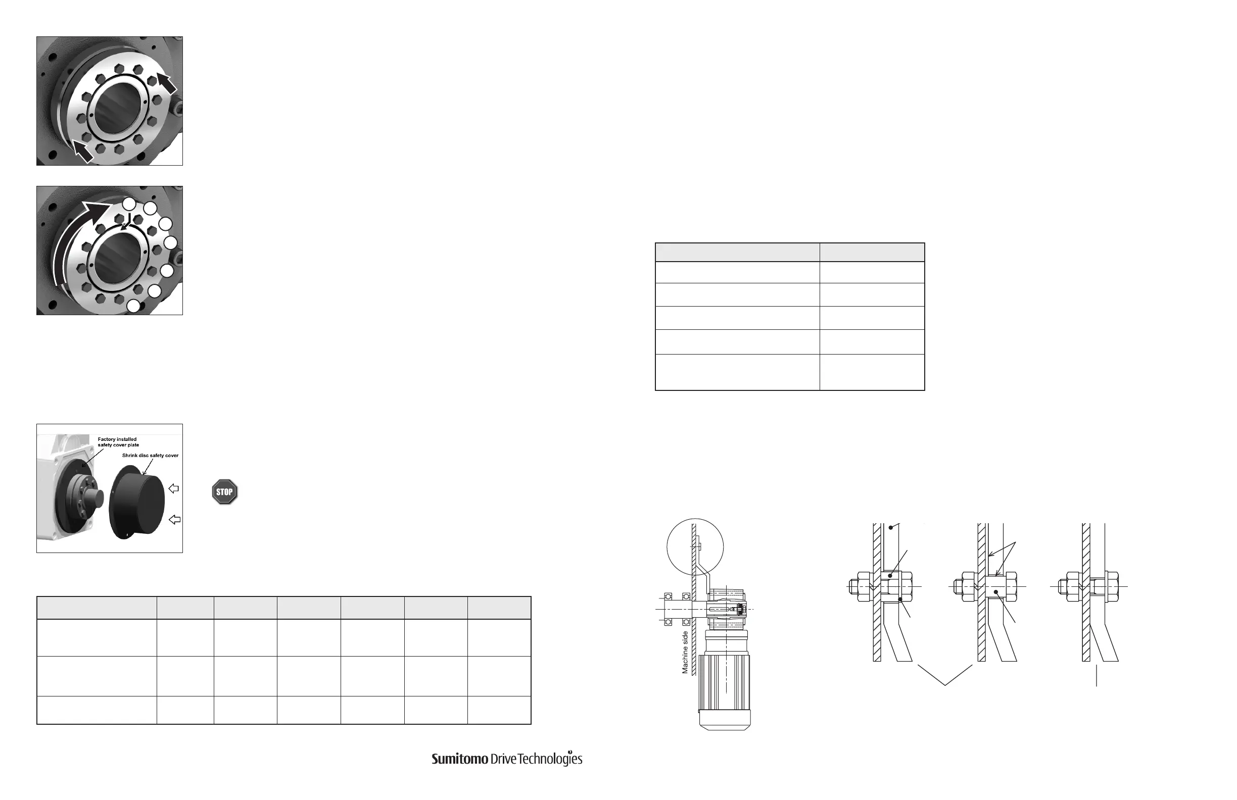
Mount the torque arm on the driven machine side of the drive casing. Use hexagon socket head bolts
for mounting. (See Table 4 for bolt sizes.)
The torque arm should be mounted to ensure that the contact surface between the drive and shaft are free from
excessive forces (Figure 10). Do not attach the torque arm using anti-rotation bolts. For applications that require
frequent starts and stops or frequent reversing, insert a rubber bushing (or spacer) between the torque arm and
securing bolt in order to dampen impact load as shown in (Figure 11).
Model Bolt Size
1120,1230 M8
1220, 1330, 1340 M10
1320, 1430, 1440 M12
1420, 1530, 1531 M16
1520, 1521, 1522, 1630, 1631,
1632, 1633, 1640
M20
Table 4. Torque Arm Bolt Sizes.
No clearance betw
arm and machine
Leave some
clearance
Bolt or pin
Flat washer
Adjust clearance according to
movement of machine
Correct
Excessive force on the torque
arm bolt, machine and unit
may cause damage
Incorrect
Spacer
Fig. 10 Fig. 11
Removal Instructions
Standard Face Mount Torque Arm
Following either a clockwise or counterclockwise sequence, loosen all locking screws using approximately ½ turns, until
you can remove the shrink disc from the hub. The shrink disc, hub, and shaft will return to their original clearance fits.
Note: Locking screws do not have to be removed completely from the shrink disc.
Torque Arm Installation