28
9-1) Disassembling / assembling of gear and motor
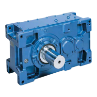
Hollow input shaft 4.
Reducer Motor
Motor assembly / disassembly direction
Motor mounting flange 1.
Mounting bolt 2.
Motor 3.
Disassembling procedure
(1) Remove mounting bolts .2.
(2) Separate motor
Carefully handle them not to touch the edge of key and the output shaft end of bushing
otherwise, coating of bushing may be come off.
and motor ;
from gear reducer.3.
5. 3.
5.
9-2) Disassembling / Assembling of motor
Please pay particular attention to followings when motor's disassembled or assembled.
(1) Carefully handle bearing and winding not to be adhered with dust and liquid.
(2) Apply a little bit amount of adhesive to outer diameter of bearing in the case of overloading usage such as
large loading fluctuations and vibration (Recommended adhesive: Locktite 242 or 271).
(3) After removing old non-drying liquid gasket, apply new one.
(4) Make sure that there are no abnormalities by rotating with hands befoer the trial run.
COMMON
9. Disassembly / reassembly
•
Keep hands and all foreign objects from keyway and other sharp edges of parts; otherwise, injury may
occur.
•
Disassemble them at a clean, dry location.
•
Keep accessory parts like screws in the box to prevent loss.
•
Carefully handle parts to prevent damage.
•
Repair, disassembly, and reassembly should be handled by properly technicians; otherwise, the system may be
damaged.
CAUTION
Fig.36
Assembling procedure
(1) Install gear part to where motor would be easily mounted.3.
(2) Carefully slide motor into position in the gear reducer.3.
(3) Adjust phases of motor 's output shaft key and of hollow input shaft 's keyway.3. 4.
(4) Apply grease t output shaft of motor
Carefully handle them not to touch the edge of key and the output shaft end of bushing
otherwise, coating of bushing may be come off.
and motor ;
and insert it into hollow input shaft slowly.3. 4.
5. 3.
5.
(5) Check whether motor
motor.
is properly inserted and tighten installation bolt to fix motor with flange for3. 2. 3.
!
Bushing 5.
 Loading...