
S
Scott McmahonAug 3, 2025
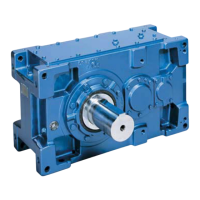
How to fix Sumitomo PARAMAX 9000 motor that will not operate under no load?
- NNichole BradshawAug 3, 2025
If your Sumitomo Industrial Equipment motor isn't operating under no load, there could be several reasons. It could be due to a power failure, in which case you should contact the electric power company. Alternatively, check the circuit for defects, replace any blown fuses, or ensure that a protective device isn't engaged. Also, verify that the load isn't locking and adjust the switch contact area if it's poor. If the 3-phase is functioning as single-phase, check the power supply with a voltmeter and inspect the motor, coil in the transformer, contactor, and fuse; repair or replace them as needed.