12 Summit 3000 Installation Manual
4.3 Load Cell Replacement
Replacement load cells can be ordered from Rice Lake Weighing Systems.
Lift the scale with a chain, spreader bar and the provided eyebolt. Remove the foot and the defective load cell.
Disconnect load cell cable from the junction box and cut cable ties. When the cable is freed, pull cable out of the
scale frame channels.
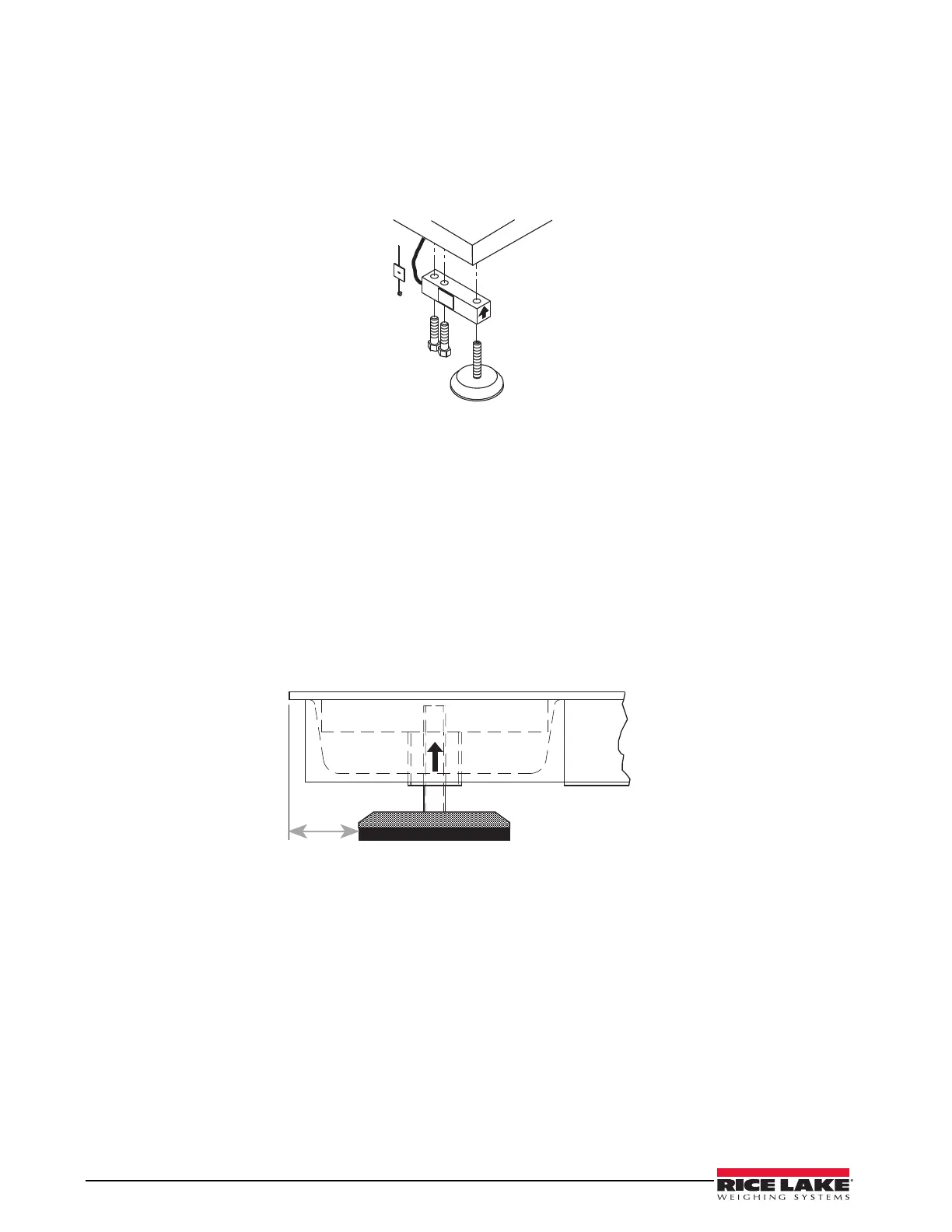
Figure 4-1. Load Cell Assembly
Use the following directions to install new load cells.
1. Lay out the load cell near the corner where it is to be installed.
2. Thread the cable from the load cell through the frame and into the junction box. Use the terminal
numbers inside the junction box to match the cable.
3. Check that the threaded holes for the load cell screws are free of debris. Use compressed air to blow out
holes if necessary.
4. Position load cells with alignment arrows pointed up toward the deck.
5. Loosely install the hex head cap screws provided, as shown in Figure 4-1. If the base is used with a pit
frame or access ramp, position the load cell to maintain the dimension shown in Figure 4-2.
6. With the torque wrench, tighten all bolts to 75 ft-lbs.
Figure 4-2. Foot Pad - Side View
7. Route the load cell cables near each corner so that the cable is free from possible contact with each foot.
Hold the cable in position with the supplied adhesive-backed cable ties.
8. Do not cut load cell cables. Coil extra cable before it enters the junction box, tie with cable ties, and
insert the coils into the channel near the junction box.
9. After coiling excess cable, pass each individual end of load cell cable through its grommet in the
junction box cover (or through cable fittings in the NEMA 4X junction box).
Corner correction trimming and calibration is necessary after load cell replacement. Follow instruction in
Section 3.2 and 3.3.
2000 to 10,000 models: 1.625"