I T L S E R V I C E M A N U A L
H-14
HYDRAULIC SYSTEM
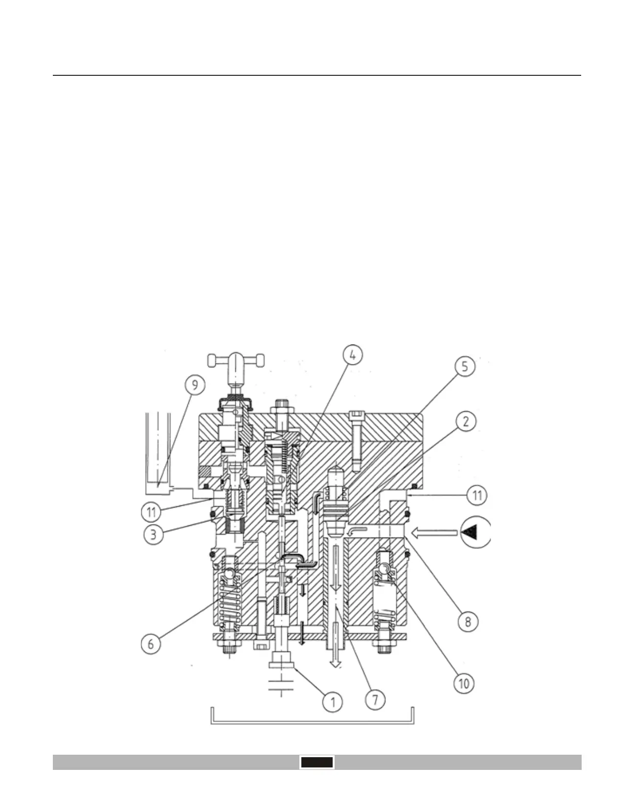
H 6.0 OPERATION OF POWER LIFT CONTROL VALVE ON- OFF
In this phase the control valve keeps pressure on the oil contained in the cylinder thus allowing the oil coming from the
pump to flow freely to the tank.
The oil contained in the cylinder (Chamber 9) is kept under pressure by the check valve “3”, by the discharge valve “4”
and by the safety valve “10” connected to the cylinder “9” by the annular duct “11” thus holding the load applied to the
lifting arms.
Neutral Phase
The safety valve “10” secures protection from any possible over pressure during the implement movement.
The oil coming from the pump enter the annular duct “8” will thus be able to move the differential valve “2” downward
and thus opens the discharge hole “7” and the oil will flow to the tank.
In this phase the control spool “1” is in such a position to connect the chamber “5” of the differential valve “2” directly to
the discharge through hole “6”.
The control valve is pre-set to obtain three distinct phases:
Neutral Phase
Delivery Phase
Discharge Phase
 Loading...