6
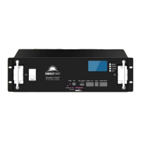
5. Definition of battery system interface
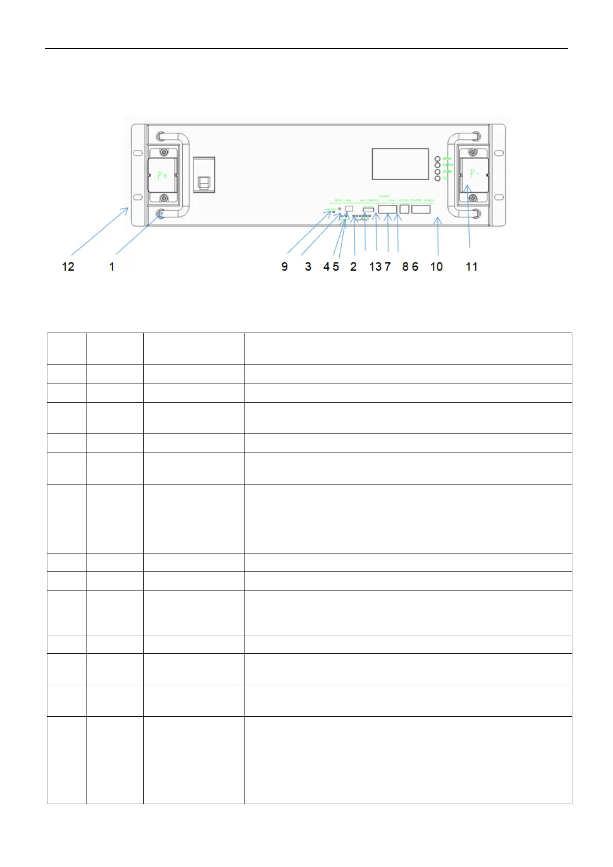
5.1. Panel Schematic
5.2. Module Panel Description
Six green LED lights to show the current charge of the lithium battery pack
Red LED light, normally off under normal conditions, always on under
fault conditions, and a voice prompt
Green light, always on when the product is running
Use 4 bit binary DIP switch (optional) to set address allocation when
products are used in parallel,
Uplink communication port, RS232 communication mode when uploading
data, data content includes system parameters, system status and alarm
information. The rate of 9600bps is generally used. Note: Wiring
definitions are implemented in accordance with BMS product
specifications
RS485 communication method
When the product is in an abnormal state or in a hibernation state, the
product can be restarted and woken up through the reset button to ensure
the stable operation of the system
Sheet metal thickness 1.5mm, galvanized frosted paint, color: black
Input and output
terminals
Battery positive and negative output terminals
The spacing is implemented according to the national standard
example:
definition:
Dry contact 1-PIN1 to PIN2: normally open, closed during fault protection
Dry contacts 2-PIN3 to PIN4: normally open, SOC<5%, closed for low
battery alarm.
 Loading...