-14-
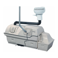
EXCEL AC/DC PART NUMBERS & DESCRIPTIONS
# PART DESCRIPTION # PART DESCRIPTION
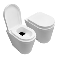
1 EN-0208 TOILET SEAT 26 EN-0173 NYLON DRIVE GEAR
2 EN-0246E BOWL LINER 27 EN-0194 DRUM SCREEN
3 EN-0249 NYLON DRUM HINGES 28 EN-0104 EXCEL TANK
4 EN-0127 EXCEL DRUM DOOR 29 EN-0571 OVERFLOW DRAIN
5 EN-0107B
EN-0108B
EXCEL COMPOSTING DRUM 30 EN-0310 THERMOSTAT
6 EN-0588 MIXING BAFFLE 31 EN-0120 THERMOSTAT ACCESS PORT
7 EN-0126B DRUM LOCK MECHANISM 32 EN-0155 HEATER
8 EN-0111B FRONT BEARING PLATE 33 EN-0187 INSULATION
9 EN-0113 HUMUS DEFLECTOR 34 EN-0197 AIR INTAKE
10 DRUM HANDLE 35 EN-0188 RUBBER “U” CHANEL
11 EN-0198 FOOTREST CHANNEL 36 EN-0106 EXCEL HEATER TRAY
12 DRUM LOCK RELEASE
13 EN-0109 FINISHING DRAWER
14 EN-0122B FOOTREST
15 EN-0119 FAN COVER
16 EN-0135 FAN CORD
17 EN-0181 POWER CORD
18 EN-0128 FAN DOOR COVER
19 EN-0232 90
O
VENT INTAKE
20 EN-0129 FAN
21 EN-0305 4" NON-ELECTRIC VENT
22 EN-0101 EXCEL TOP
23 EN-0248 FLAT HD. SCREW (#8X
e” SS)
24 EN-0111B REAR BEARING PLATE
25 EN-0267 ROLL PIN (5/32 X 1¾” SS)
-7-
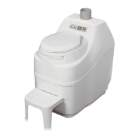
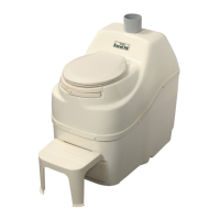
INSTALLATION
Inspection
Inspect for
Damage
Remove the "EXCEL AC/DC" carefully from carton. If the product has been damaged,
contact Sun-Mar to determine the best course of action, and :
i) Note the damage description on the shipping papers.
ii) If the shipper has left, report the damage immediately to the transport Company.
Check Carton
Contents
and
Familiarize
yourself with
the Product.
Check that the carton contains both the 2" and 4" vent stacks (pipe, fittings, roof flashings,
insulation, diffusors, a 12 Volt fan for installation in the base of the 4" vent stack), peat
moss mix, and rake.
i) Turn the drum handle clockwise to rotate the Bio-drum for mixing and aeration.
(The drum rotates counter-clockwise and the drum door shuts).
ii) Depress the drum stopper under bowl liner (1993 and prior) or pull the stopper on
the front of the unit (1994 and on) and turn the handle anti-clockwise to simulate
extraction of compost.
(The Bio-drum rotates clockwise and drum door remains open).
iii) If 110 volt power is available, plug the unit’s electrical cord into a standard electrical
outlet, and put your hand at the top rear of the unit to feel the air movement caused
by the fan.
iv) Pull out the compost finishing drawer (situated below the drum) where the compost
drops for finishing.
v) After the unit has been plugged in for five minutes, place your hand on the floor of
the evaporating chamber (underneath where the drawer was) to check it is warm to
the hand, and the heater and thermostat are functioning properly.
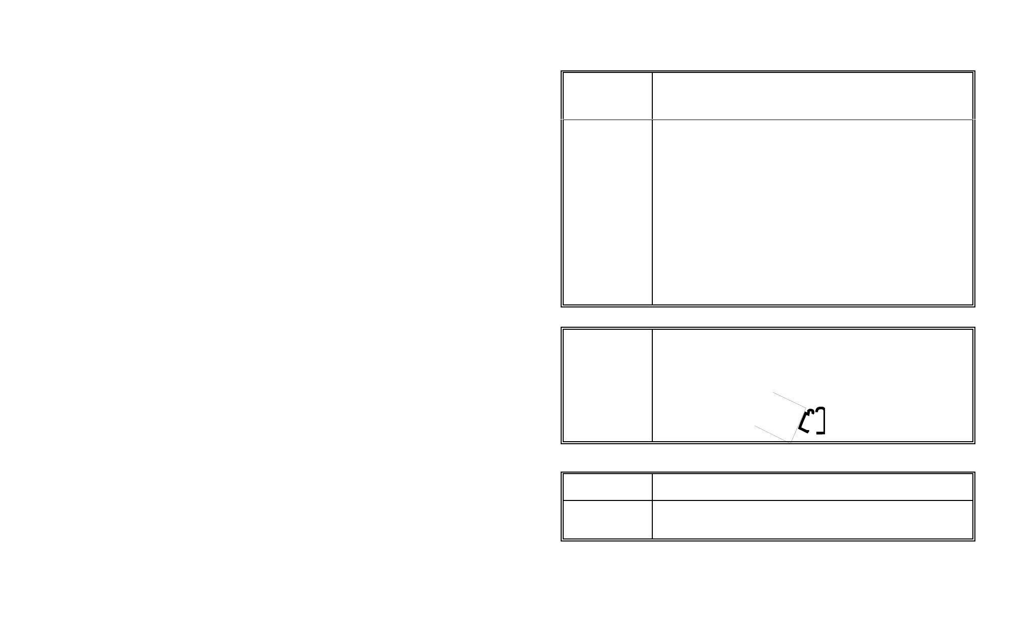
Attaching the Footrest
Attaching and
detaching the
footrest
The footrest attaches to the unit into the slot above the drawer by inclining the footrest at
a 45
o
angle to the floor, inserting the round top edge of the footrest profile into the round
top edge of the profile on the unit, and lowering the footrest to the floor. It is detached in
the same way, whenever it is necessary to remove the finishing drawer, by lifting the
footrest until it is at a 45
o
angle and then withdrawing it.
Note: The footrest is designed as a footrest, it is NOT designed for standing on.
Installing the Toilet
Space Required
When selecting the best place for your toilet, make sure that there is room (an extra 20" is
required) to remove the finishing drawer from time to time.
Other
Considerations
The location of the vent stack, and perhaps the emergency drain may determine the best
place for the toilet. Ensure that the toilet is level front to back or is sloping slightly
backwards. The unit should not tip forward.
 Loading...