WARNING: When the power of PV module is greater than the rated
chargingpower, and the maximum open-circuitvoltageof PV array is more
than 96V (at the lowest environmental temperature), the controller may be
damaged.
According to “Peak Sun Hours diagram”, if the power of PV array exceeds the rated
charging power of controller, then the charging time as per the rated power will be
prolonged, so that more energy can be obtained for charging the battery. However, in
the practical application, the maximum power of PV array shall be not greater than 1.5
x the rated charging power of controller. If the maximum power of PV array exceeds
the rated charging power of controller too much, it will not only cause the waste of PV
modules, but also increase the open-circuit voltage of PV array due to the influence of
environmental temperature, which may make the probability of damage to the
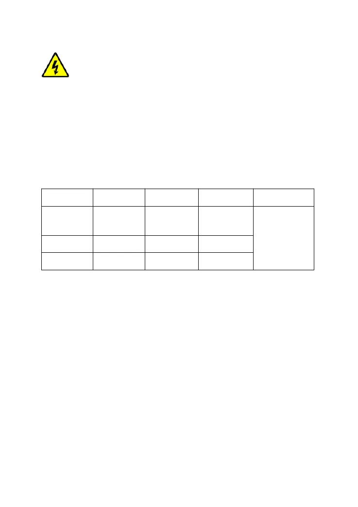
controller rise. Therefore, it is very important to configure the system reasonably. For
the recommended maximum power of PV array for this controller, please refer to the
table below:
Model
-M4024 40A
520W/12V
1040W/24V
780W/12V
1560W/24V
①At 25℃ environmenttemperature
②At minimum operating environmenttemperature
2.3 WireSize
The wiring and installation methods must conform to all national and local electrical
code requirements.
PV Wire Size
Since PV array output can vary due to the PV module size, connection method or
sunlight angle, the minimum wire size can be calculated by the Isc
*
of PV array.
Please refer to the value of Isc in the PV module specification. When PV modules
connect in series, the Isc is equal to a PV modules Isc. When PV modules connect in
parallel, the Isc is equal to the sum of the PV module’s Isc. The Isc of the PV array
must not exceed the controller’s maximum PV input current. Please refer to the table
as below:
NOTE: All PV modules in a given array are assumed to be identical.
*Isc=short circuit current(amps) Voc=open circuit voltage.
9