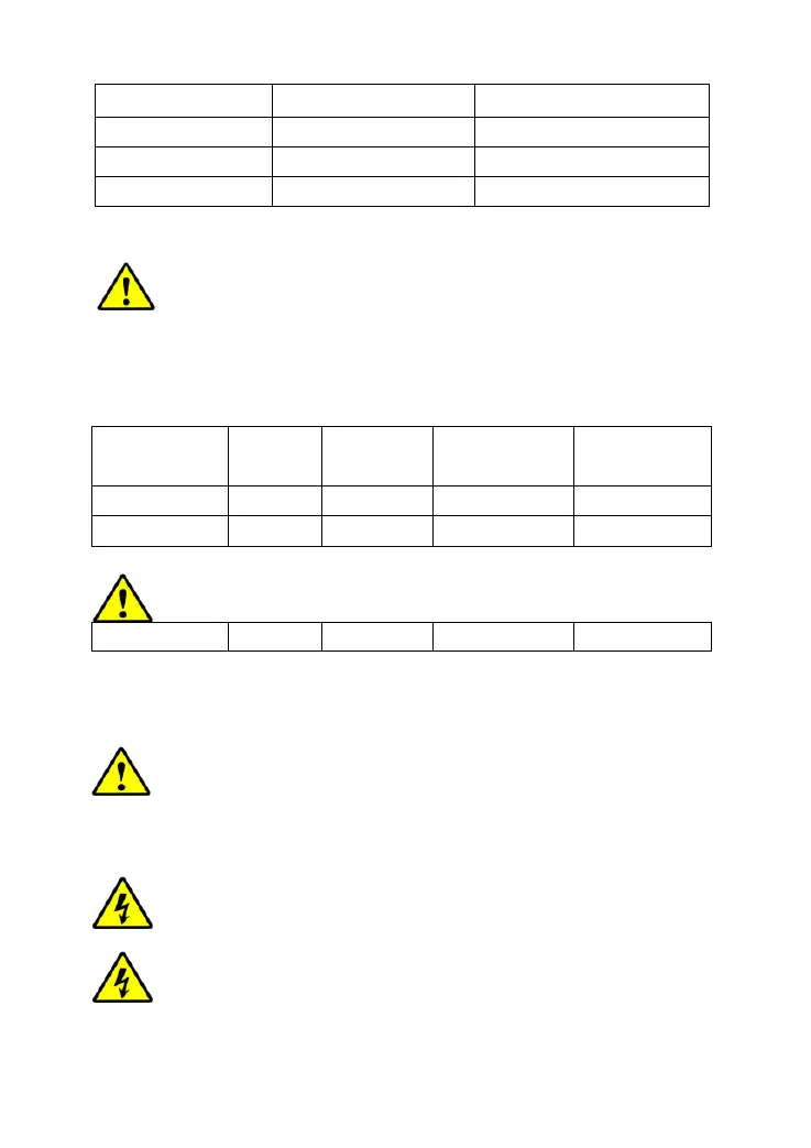
Model Max. PV input current
Max. PV wire size
*
MAX-M2024 20A 6mm
2
/10AWG
MAX-M3024 30A 10mm
2
/8AWG
MAX-M4024 40A 16mm
2
/6AWG
*These are the maximum wire sizes that will fit the controller terminals.
CAUTION: When the PV modules connect in series, the open circuit
voltage of the PV array must not exceed 92V at 25℃ environment
temperature.
Battery and Load Wire Size
The battery and load wire size must conform to the rated current, the reference size
as below:
Model
Rated
charge
current
Rated
discharg
current
Batterywire
size
Loadwire
size
MAX-M2024 20A 20A 6mm
2
/10AWG 6mm
2
/10AWG
MAX-M3024 30A 30A 10mm
2
/8AWG 10mm
2
/8AWG
MAX-M4024 40A 40A 16mm
2
/6AWG 16mm
2
/6AWG
CAUTION: The wire size is only for reference. If there is a long distance between the
PV array and the controller or between the controller and the battery, larger wires can
be used to reduce the voltage drop and improve performance.
CAUTION: For the battery, the recommended wire will be selected
according to the conditions that its terminals are not connected to any
additionalinverter.
2.4 Mounting
WARNING: Risk of explosion! Never install the controller in a sealed
enclose with flooded batteries! Do not install in a confined area where
battery gas can accumulate.
WARNING: Risk of electric shock! When wiring the solar modules, the PV
array can produce open circuit voltages in excess of 100V when in
sunlight.
10