9 of 17
• Always wire modules so that proper polarity is maintained. Avoid placing excessive tension on the cables.
• There is no limit to the maximum number of series strings that can be combined in parallel. However, when doing so,
each string must include overcurrent protection with a maximum rating of 15A. SunEdison recommends the use of DC
rated fuses or overcurrent protection devices with the appropriate maximum voltage rating.
• Do not connect modules directly to a parallel bus.
• The cross-sectional area of cable and the connector type must be selected to align with the overall system design
and should include the maximum short circuit current of the system, maximum operating temperatures, and cable run
lengths.
• For field connections, use at a minimum #12 AWG/4 mm
2
wires insulated for a minimum of 85°C. Use copper wire only.
5.3 GROUNDING
The frame of the PV module as well as any exposed metal components that can become energized by the PV system
MUST be connected to an equipment grounding connector to prevent electrical shock. Refer to section 250 of the
NEC for specific instructions on grounding. Even when local regulations, codes, or standards do not require safety
related grounding, SunEdison highly recommends grounding all PV module frames in order to maintain a zero-voltage
potential between electrically conductive equipment and the earth in all scenarios. Proper grounding is obtained by
bonding all exposed metal equipment to each other by using a properly sized equiptment grounding conductor (EGC).
SunEdison PV modules use a coated aluminum frame for corrosion resistance. In order to ensure proper grounding
the coating must be punctured by the grounding method. A grounding wire composed of copper with a minimum
guage of 12 AWG is recommended to carry the electrical ground load. Consult applicable codes to see if a larger
diameter conductor is required. The potential for corrosion due to the electrochemical reaction between two
dissimilar metals in contact is minimized if the voltage potential between the two metals is low. The grounding
method must not allow for the direct contact of dissimilar metals with the frame of the module, which would result in
galvanic corrosion. UL 1703 recommends metal combinations not exceed a voltage potential of 0.5 Volts.
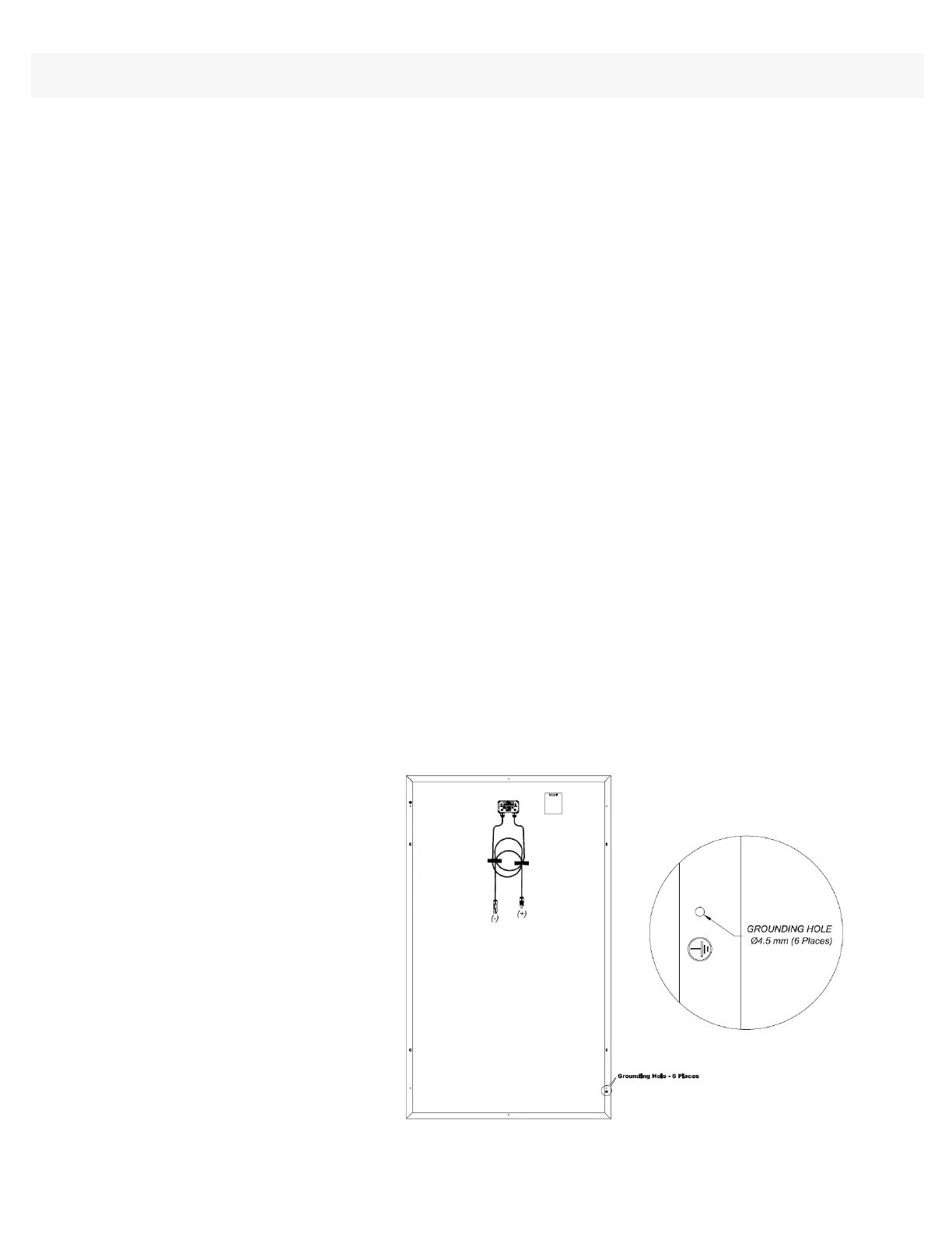
The frame has predrilled holes marked with a grounding sign as illustrated below. These holes should be used
exclusively for grounding purposes, and may not be used for any other purpose. Do not drill additional holes or
modify existing holes in the frame.
WARNING: Only negative grounding circuits (negative polarity to ground) shall be used within the array design.
Transformerless inverters with floating grounding are not acceptable.
Figure 2: Image of the grounding holes
Installation Manual: SunEdison Silvantis P300 | M330/F330/D330
© Copyright 2014 SunEdison, Inc.