5000A 3 rev. 11/04/13
Parts
Unpack carton, check your machine to see parts listed
below:
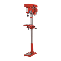
A. Main Parts
1. Head Assembly 1 Pc.
2. Column with Flange 1 Pc.
3. Working Table Assembly 1 Pc.
4. Base 1 Pc.
B. Accessories (in one separate box)
1. Chuck and Key 1 Set
2. Feed handles with knobs 3 Pcs.
3. Column Lock Handle 1 Pc.
4. Column Flange Bolts 4 Pcs.
5. Allen wrenches (3mm & 5mm) 1 Pc.
6. Arbor 1 Pc.
7. Cotter 1 Pc.
8. Crank handle 1 Pc.
Assembly
1. AssembletheColumn
• Placecolumnassemblyonbaseandalignholesin
column support with holes in base.
• Secure the column with four bolts and washers
provided.
2. InstallTable
• Attachcrankhandletowormpinion.
• Removerackringandrackfromcolumnbyundoing
set screw with allen wrench.
• Slide rack and table assembly over column and
replace rack ring.
• Securetableassemblywithcolumnlockhandle.
3. AttachHeadtoColumn
• Carefully put the head assembly over column and
slide it onto column into position. Align head frame
with table and base. Fix set screw in left side of
head to lock head into position then tighten with
allen wrench.
4. InstalltheFeedingHandles
• Screwtheknobstothefeedinghandles
• Screw each feeding handle into hub of pinion
shaft.
5. AttachtheChuck
• Positionworkingtableup about5”(125mm) from
the tip of spindle.
• Removealloilandgreasefromtapersonarborand
drill chuck.
• Slideshortendofarborintochuck.Placelongend
inside spindle.
• Open chuck jaws completely by turning attached
chuck key counter clockwise to the end.
• Putapieceofscrapwoodonthetabletoprotect
chuck nose.
• Pull feeding handle down pressing the chuck
against the scrap wood until arbor is secure on the
spindle.
Adjustment
1.TableAdjustment
A. Mounting the drill press:
Your drill press must be securely fastened by
the two base holes to a floor with heavy-duty
fasteners. This will prevent the drill press from
tipping over, sliding, or walking during operation.
B. Height Adjustment:
To adjust up or down, loosen the column lock
handle, then turn crank handle to desired height.
Retighten column lock handle before drilling.
C. TiltingAdjustment:
Loosen pivot bolt. Remove small locator pin.
Tilt table to desired angle up to 45° and retighten
bolt. Re-insert locator pin when returning table to
zero degrees.
D. Swing 360°
Loosen lock handle then swing table to appropriate
position and retighten.
E. Rotate 360°
Loosen table lock handle, rotate table to desired
position and retighten.
2. DepthAdjustment
A. Feed Depth Adjustment
Loosen scale set knob on feed shaft assembly.
Rotate spindle gauge to desired depth and tighten
scale set knob.
B. Stationary Depth
Loosen scale set knob. Turn feed shaft to lowest
point then rotate spindle depth to desired depth
and retighten scale set knob.
3. SpeedAdjustment
A. Loosen the slide bar bolt on right hand side
of head.
B. Slide motor toward front of drill press and tighten
the slide bar bolt.
C. Relocate the belts to the correct pulleys for the
required spindle speed.
D. Loosen slide bar bolt and slide motor toward rear
of drill press and tighten the slide bar bolt.
 Loading...