SunFounder GalaxyRVR Kit for Arduino, Release 1.0
(continued from previous page)
pinMode(in4, OUTPUT);
}
void loop() {
digitalWrite(in3, LOW);
digitalWrite(in4, HIGH);
}
Here, we define two variables to represent pins 4 and 5. By using variables, we can easily manage
and adjust our pin assignments throughout our code.
Think of it as if we’re assigning a specific role or duty to each pin number. When we decide to
reassign the roles, instead of going through the entire script and changing every instance, we just
update the assignment at the beginning of the script (where the variable is initially defined).
• 4. About Drive Logic
1. In the previous tests, you would have noticed that the motors all spin in one direction. How do we make
it spin in the opposite direction? Someone might suggest swapping the HIGH and LOW of the two pins.
That’s correct.
const int in3 = 4;
const int in4 = 5;
void setup() {
pinMode(in3, OUTPUT);
pinMode(in4, OUTPUT);
}
void loop() {
digitalWrite(in3, HIGH);
digitalWrite(in4, LOW);
}
Once you’ve written your code and uploaded it to your Arduino board, the motor will behave as
instructed.
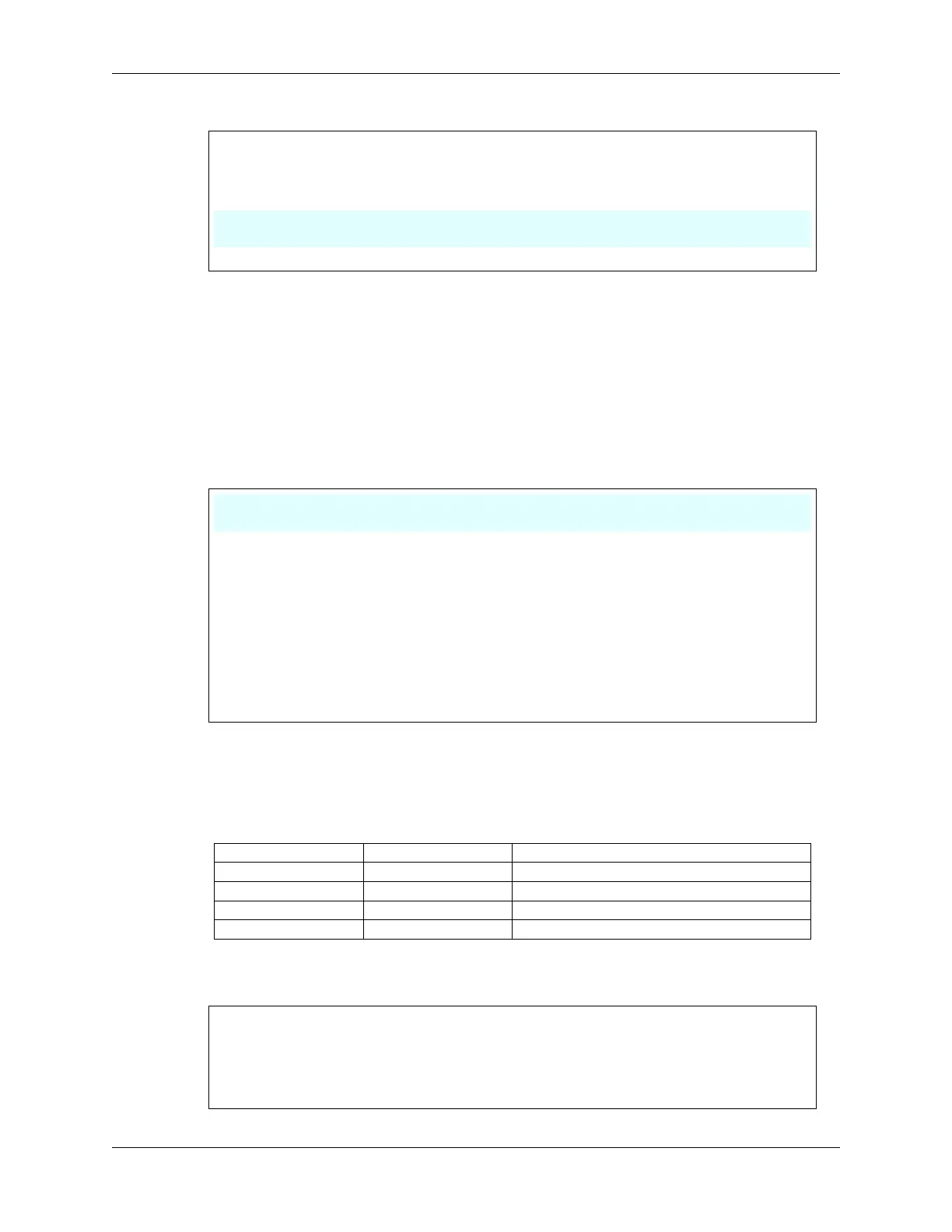
2. Let’s now look at the internal driving logic of the drive chip.
INA INB Motor
L L Standby
L H Clockwise
H L Counterclockwise
H H Brake
3. Now, let’s try to make the motor rotate clockwise for 2 seconds, counterclockwise for 2 seconds, and then
stop.
const int in3 = 4;
const int in4 = 5;
void setup() {
pinMode(in3, OUTPUT);
(continues on next page)
40 Chapter 3. Course Mode