SunFounder GalaxyRVR Kit for Arduino, Release 1.0
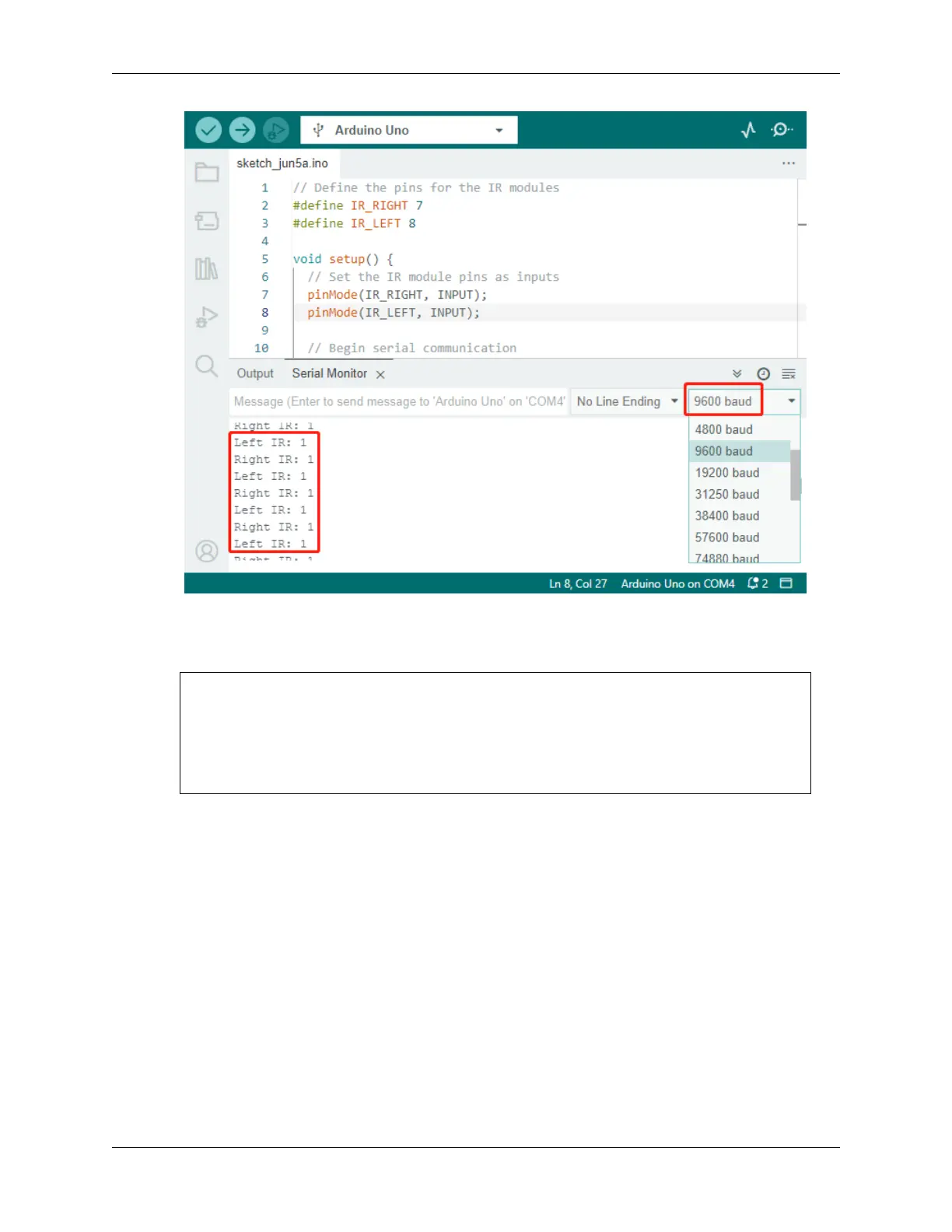
5. To put our system to the test, wave a “space rock” (your hand) in front of one of the sensors. You’ll see the value
flip to 0, and the corresponding LED on the module lights up. That’s the Rover saying, “Look out, space rock on
my right!”
Right IR: 0
Left IR: 1
Right IR: 0
Left IR: 1
Right IR: 0
Left IR: 1
By now, you’ve not just journeyed through space but also deciphered Martian! Can’t wait to see what interstellar secrets
we unveil in our next mission!
Step 4: Adjusting the Detection Distance
We have arrived at an essential step, which is to adjust the detection distances of our sensors based on our current
environment. The factory settings may not be optimal.
If the detection distance of the two infrared modules is too short, the Mars Rover might collide with obstacles. If it’s too
far, the Rover might start turning while still a significant distance from an obstacle, potentially impacting its movement.
Here’s how you can make adjustments:
1. Start by adjusting the right obstacle avoidance module. During transportation, collisions may cause the trans-
mitter and receiver on the infrared module to tilt. Therefore, you need to manually straighten them.
2. Place an obstacle about 20 cm directly in front of the right module. The box in which our Rover kit came is
a good choice for this! Now, turn the potentiometer on the module until the indicator light on the module just
56 Chapter 3. Course Mode
 Loading...