7 8
toggled in before delivery, if need to change the input voltage, please
toggle the switch cap into correct position before power on .
The 24V DC brushless/servo motor has 8 wires connected to control board.
Power supplies output 24/12V DC to control board, one is supply power to
motor, one is supply power to control unit.
7.1.4. R&G (LED) light power supply:
There is power supply specially for R&G light, if you connect to 24V or
12V power supply, the R&G light input should be consistent.
7.1.5. R&G light interface:
When boom falling down to horizontal position, red light will
keep lighting; when boom lifting up to vertical position, green light will
keep lighting. During the boom falling down or lifting up, the red light will
keep lighting. (Please refer to Appendix III for wire diagram)
The interface also can be used to output open limit signal and close limit
signal, Please check wiring Figure 4 for reference(Optional output).
7.1.6. Wire control signal input interface:
This interface is dry contact input signal, UP/ DOWN / STOP connect
with
“COM ”, the control board will respond accordingly. User can use
this interface to connect with parking system, and it can
also wiring connected to button switch to control the barrier. (Please refer
to Figure 4 for for main control board wire control)
7.1.7. Photocells interface:
This interface is dry contact input signal, only for responding opening
when
shorts circuit the terminal “Photocells” during closing. This is
mostly use for prevent damage when boom falling. So normally
photocells are installed paralleled and under the arm. Boom will keep
open, or will auto-reverse when there are obstacles between photocells.
7.1.8. Loop detector interface:
This interface is dry contact input signal, only for responding to au t o
cl o s ing aft er signal input and then disa p p e a r ed. So first it
should received dry contact or re l ay inp u t , after the input
signa l di s appeared, bo o m wil l auto fal l i ng to closed
This interface is used for communication between computer and
SFMCU control unit. We provide SDK for customers to develop
software to receive barrier gate status and control barrier gate
7.1.10. Battery interface:
This interface is used for battery, the battery can be used to keep
barrier gate working normal when power off.
7.1.11. Other interface(Arm detection):
Currently it’s used for arm detection. This function is not open
unless needed, you can open this function from menu settings.
Please see Appendix VI for reference.
3 buttons for menu setting, INC, SET, DEC, setting guidance please refer
7.1.13. Manual control button
‘UP’, ‘DOWN’, ‘STOP’ , these 3 buttons allow you to control barrier
gate open, close and stop by manual. The stop button also used as save
7.2. Controller auto-detect after power-on description.
When the arm is in open position, the controller should re-confirm the close
position of boom after power-on or resume power: The barrier gate will
auto close slowly one time by default. This require the boom are installed,
if not controller can not close to right position. During the re-confirming
process, it detects all open and anti-bumping signal interface, and it will
stop learning if there is signal. After finish leaning, the boom stays at the
down limit position and Buzzer will beep one time.
If spring installed but no boom, or there is obstacles on the boom during
down process, or the spring and boom in serious imbalance, need to
remove the obstruction or adjust the spring, then power-on again.
If boom is in closing position when, please do not hold or stop the arm
move, the barrier gate will confirm it’s close position very soon.
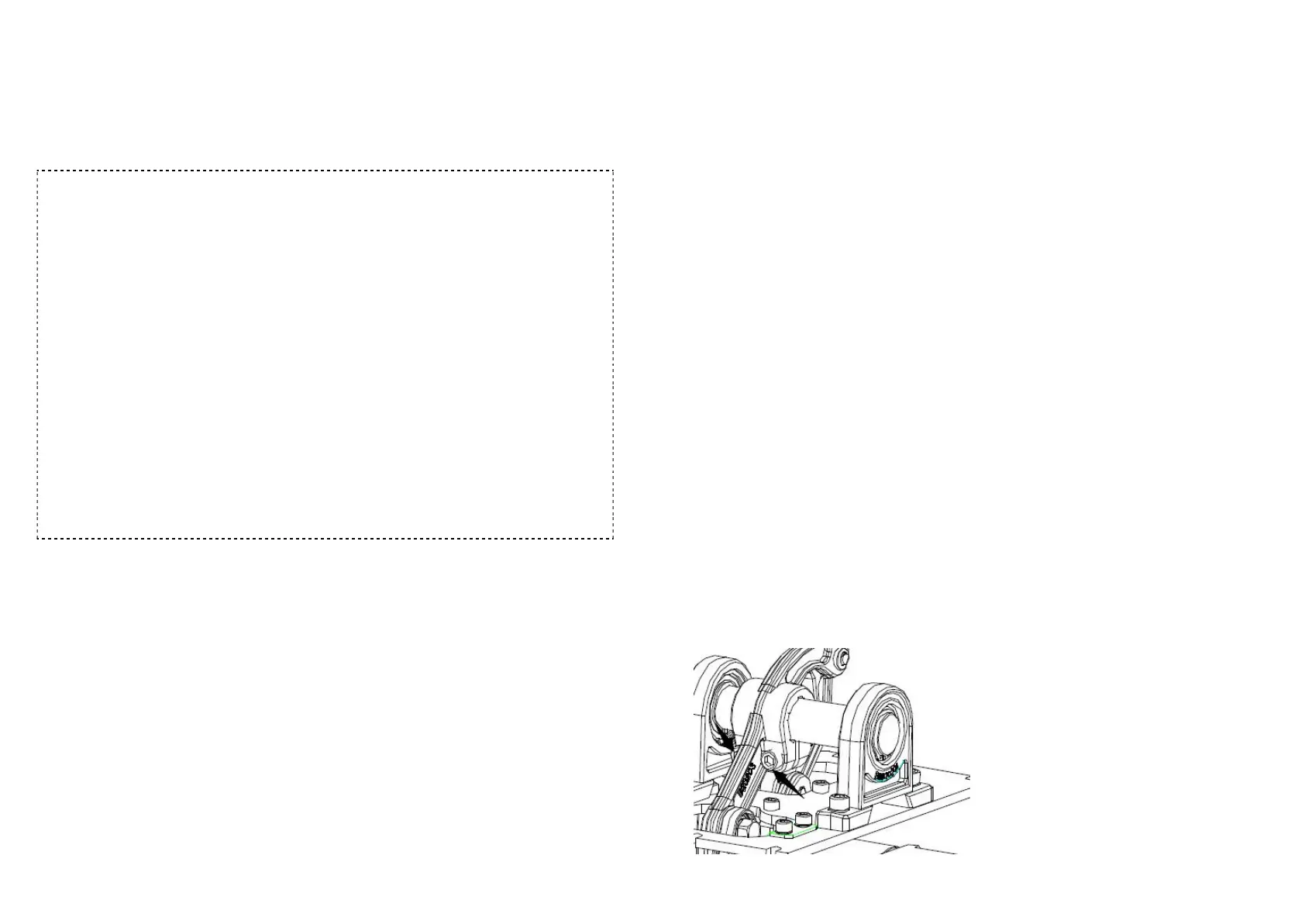
8. Boom horizontal and vertical fine adjustment
8.1 Horizontal adjustment:
Power off first. And loosen the two
screws(see figure 5) on balance
rotating arm a little but not totally
loosed, then rotate barrier arm to
make the active swing arm to
mechanical limit position. In this
situation, keep the arm in
horizontal status, and fasten the