15
5.3.1.2 Connection by Internal Grounding Point
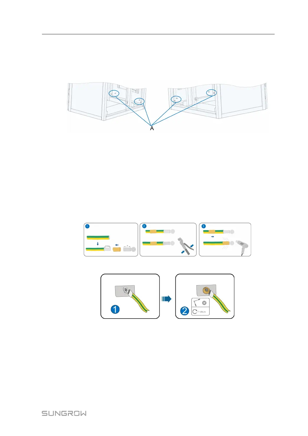
Brief Introduction
Grounding points are reserved inside the cabinet, and the positions are shown in the
following figure.
Before the combiner box leaves the factory, M6 grounding screws and flange nuts are pre-
installed on the grounding points.
Wiring Requirements
Unscrew the flange nuts on the grounding points and keep them properly for wiring.
6 mm
2
grounding cables are recommended.
Wiring Steps
step 1 Draw the external grounding cable through the inlet hole at the bottom of the cabinet.
step 2 Strip off the protective layer and insulating layer of the grounding cable to expose the copper
core part, and select the appropriate DT/OT terminal for crimping.
step 3 Place the screws, DT/OT terminals and flange nuts on the grounding points in sequence.
step 4 Tighten the nut using a socket wrench. The tightening torque is 7 ~ 8N.m.
- - End
5.3.1.3 Connection by Internal Grounding Copper Bar
Brief introduction
Grounding copper bars are reserved inside the cabinet, and their positions are shown in the
following figure.
Installation Manual 5 Electrical Connection