13
5
Electrical Connection
5.1 Internal Layout
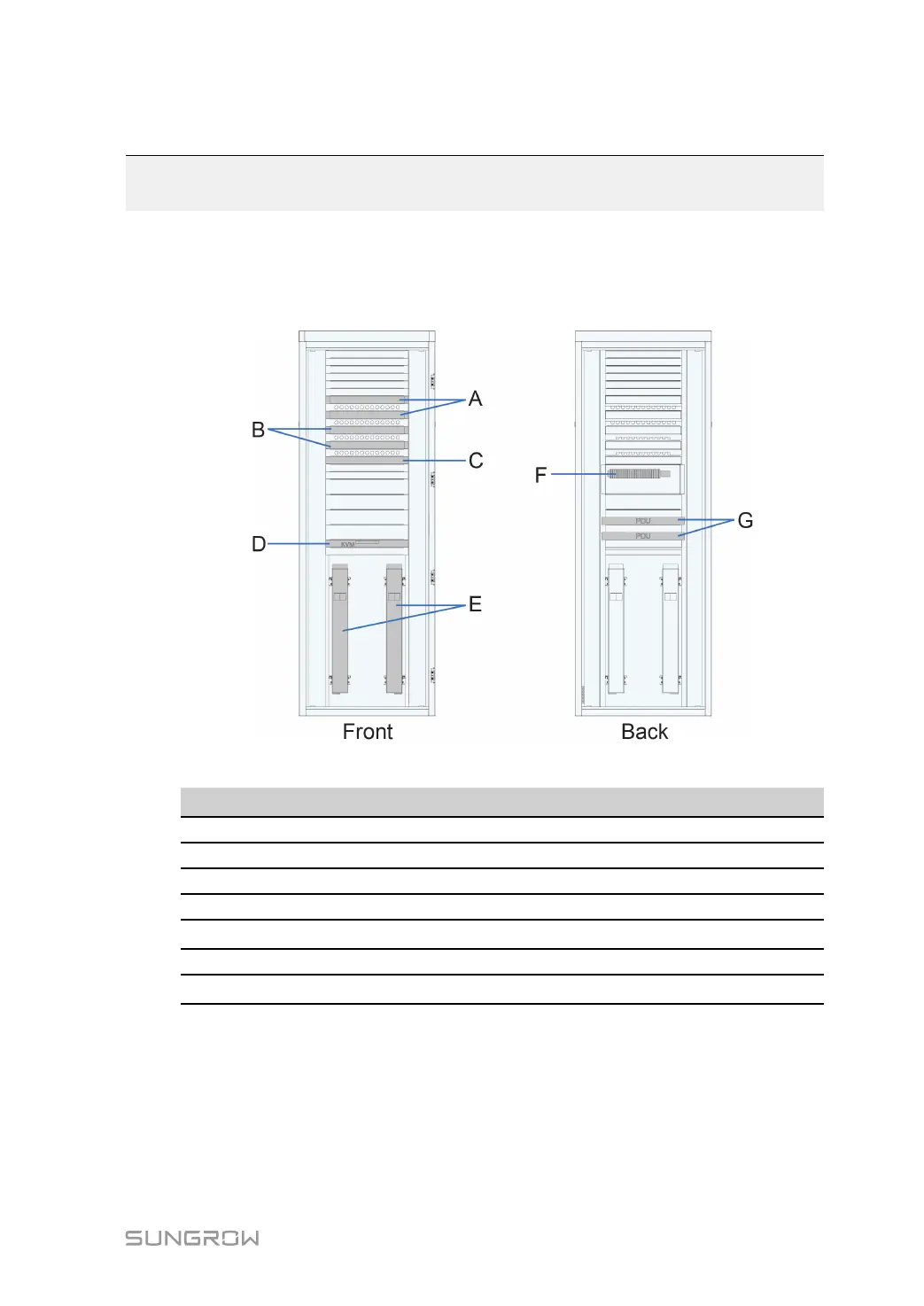
The equipment in cabinet are shown in the following figure.
The figure above is indicative only.
No.
Port type
A Controller
B Switch
C Firewall
D KVM
E
Server (optional)
F Terminal block
G
Power distribution unit (PDU)
5.2 Preparation before Wiring
The connecting cables between the product and external equipment are inserted through
the threading holes at the bottom of the cabinet.
The threading holes at the bottom of the cabinet are shown in the following figure A.