17
step 2 Connect the Ethernet ports of firewall to external devices with CAT-5e cable.
- - End
5.3.3 Optical Fibre (Optional)
step 1 Thread the fibre optic cable through the inlet hole at the bottom of the cabinet.
step 2 Splice the optical fibre inside the splice box.
For details, contact SUNGROW.
- - End
5.3.4 Connection to External Power Supply
Brief introduction
The cabinet is designed with an external power supply terminal block, which supports
connection to power supply of 100 ~ 240Vac.
5.3.4.1 Connect to a Mains Power Supply
Overview
The device is connected to a mains power supply by default, that is, the mains power is
connected to the XZ2 terminal block.
Ports Defination
Recommended specifications
XZ2–1
Connect to L phase of external
power supply
2.5mm
2
XZ2–3
Connect to N phase of external
power supply
2.5mm
2
Wiring Steps
step 1 Draw the external power supply cable through the inlet hole at the bottom of the cabinet.
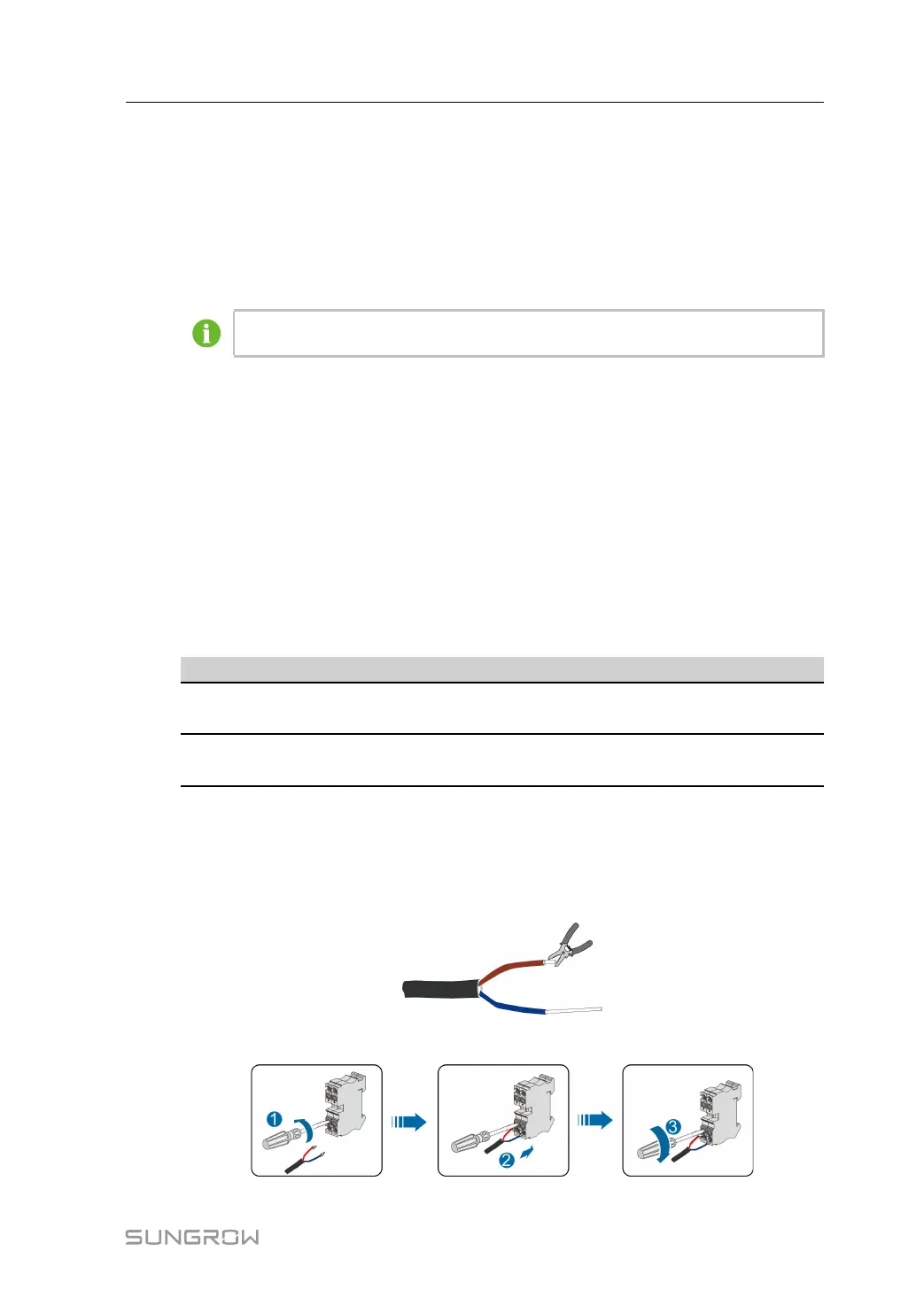
step 2 Strip off the protective layer and insulating layer of the cable to expose the copper core part,
and select the appropriate cold-pressed terminal for crimping.
step 3 Connect the cold-pressed terminal to the power supply terminal block.
Installation Manual 5 Electrical Connection