15
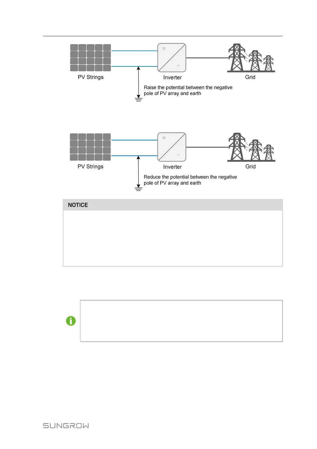
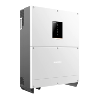
• For negative voltage scheme, after the PID function is enabled, the voltage to ground of
all PV strings is lower than 0, and therefore the PV string-to-ground voltage is a negative
value.
• Before enabling the PID recovery function, make sure the voltage polarity of the
PV modules to ground meets requirement. If there are any questions, contact
the PV module manufacturer or read its corresponding user manual.
• If the voltage scheme for the PID recovery function does not meet the require-
ment of corresponding PV modules, the PID function will not work as expected
or even damage the PV modules.
When the inverter is not running, the PID module will apply inverse voltage to PV modules,
to restore the degraded modules.
• If the PID recovery function is enabled, it only works at night.
• After the PID recovery function is enabled, the voltage of the PV strings to
ground is 500 V DC by default, and the default value can be modified through
the App.
Auto-test (for Italy CEI0-21 Grid Code Only)
The Italy CEI0-21 grid code requires auto-test for the inverter before grid connection. During
the auto-test, the inverter checks the protection threshold and protection time of the 1-level
overvoltage (59.S1), 2-level overvoltage (59.S2),1-level undervoltage (27.S1), 2-level under-
voltage (27. S2),1-level overfrequency (81>. S1), 2-level overfrequency (81>. S2), 1-level
underfrequency (81<.S1), 2-level underfrequency (81<.S2) to ensure that the inverter could
User Manual 2 Product Description