2 Product Introduction User Manual
12
Rotate the DC switch to the “ON” position, before restarting the
inverter.
2.3 Technical Description
2.3.1 Principle Description
PV strings input voltage is transmitted to DC BUS via Boost circuit.
The inverter is equipped with MPPTs for two DC inputs to ensure that the
maximum power can be utilized even in different PV modules installation
conditions.
Inversion circuit converts DC power into AC power, which will be fed into the
utility grid via five core terminals. Protective circuits are designed to guarantee
inverter safe operation and human safety.
A DC switch is integrated for safe disconnection of DC current. The inverter
provides standard interface RS485 for communication. Inverters are also
provided running records display and parameters configuration via
human-computer interface– LCD display panel.
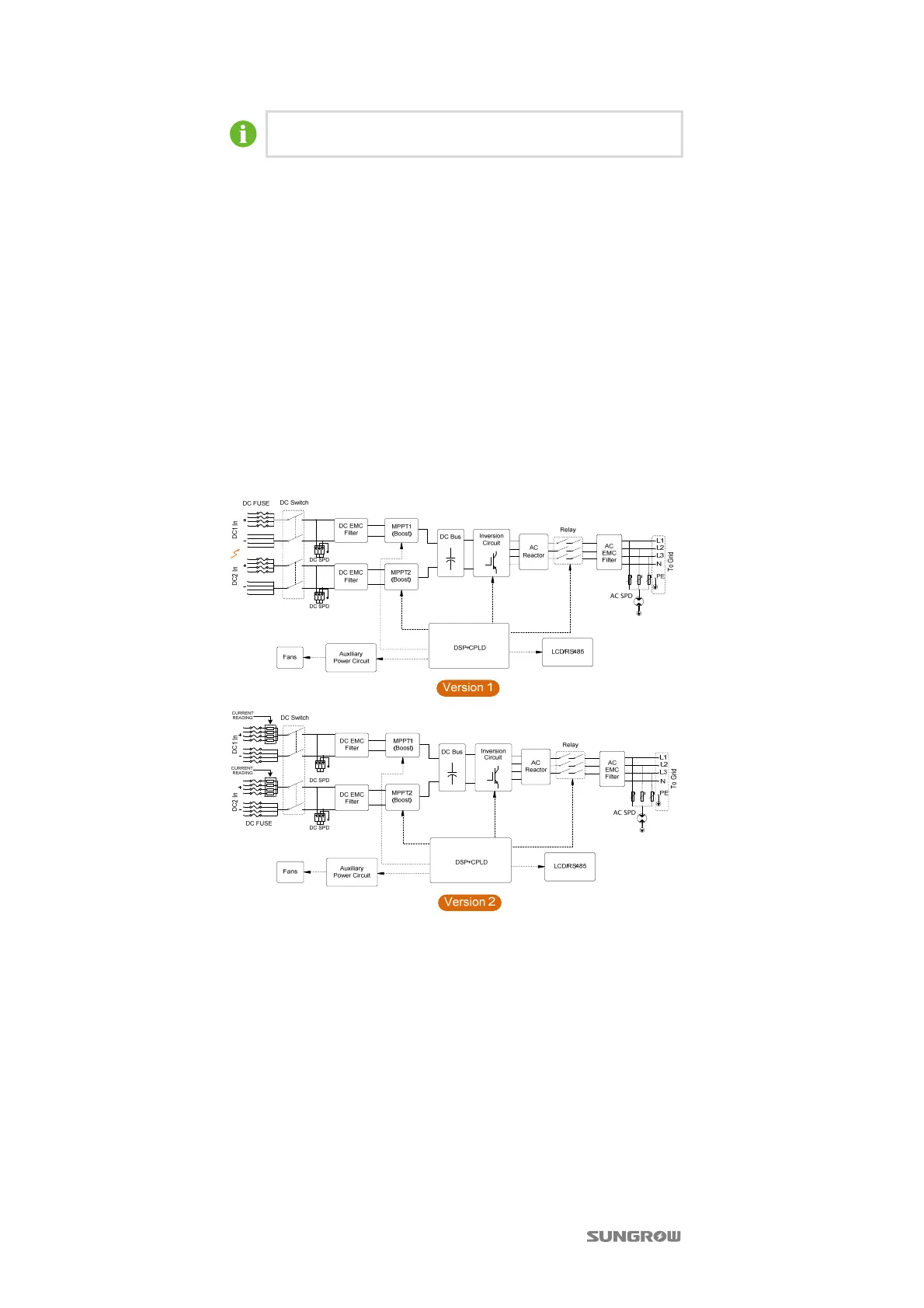
We provide 2 versions of inverters for the users, the principle design is
illustrated below:
Fig. 2-5 Main Circuit Diagram
The Version 2 inverter is equipped with Fuses for both positive and negative DC
inputs, and can detects positive fuse current.
2.3.2 Functions Description
Inverter functions can be grouped as the following:
Conversion function
Inverter converts the direct current power into alternating current power,
which conforms to the grid requirement of its installation country.
Data storage and display
Inverter stores essential data including running information and fault records,
and displays them on integrated LCD display.
Parameters configuration
 Loading...